Motor

a motor and motor shaft technology, applied in the field of motors, can solve the problems of unbalanced magnetic flux amount between the n-pole and the s-pole, unbalanced detent torque, deterioration of sound and vibration, etc., and achieve the effect of suppressing leakage flux, favorable detent torque balance, and favorable magnetic balan

Active Publication Date: 2017-07-11
DENSO CORP
View PDF9 Cites 1 Cited by
  • Summary
  • Abstract
  • Description
  • Claims
  • Application Information

AI Technical Summary

Benefits of technology

[0006]A first object of the present invention is to provide a motor which can make magnetic balance favorable by adjusting a leakage flux. A second object is to provide a motor which can make a balance of detent torque favorable. A third object is to provide a motor which can suppress the leakage flux and improve the output characteristics.
[0008]A second aspect of the present invention is a motor including a stator, a rotor, and a case. The stator has a stator core and a winding. The rotor has a first rotor core made of metal, a second rotor core made of metal, and a field magnet. Each of the first and second rotor cores having a plurality of claw-shaped magnetic poles arranged in a peripheral direction. The field magnet is sandwiched between the first rotor core and the second rotor core in an axial direction. The field magnet is configured so as to cause the claw-shaped magnetic pole of the first rotor core and the claw-shaped magnetic pole of the second rotor core to function as magnetic poles different from each other in the sandwiched state. The case is cylindrical with a bottom. The case has a yoke housing which is a magnetic body and a lid portion closing an opening portion of the yoke housing. The yoke housing accommodates the stator and the rotor. In the axial direction, the first rotor core is located closer to the lid portion than the second rotor core. The second rotor core is located closer to a bottom portion of the yoke housing than the first rotor core. The second rotor core is configured so as to be magnetically saturated less easily than the first rotor core.
[0009]A third aspect of the present invention is a motor including a stator, a rotor, and a case. The stator has a stator core having a plurality of teeth and a winding wound around the plurality of teeth. Each of the teeth extends in a radial direction. The rotor has a first rotor core, a second rotor core, and a field magnet. Each of the first and second rotor cores has a substantially disc-shaped core base and a plurality of claw-shaped magnetic poles provided at equal intervals on an outer peripheral portion of the core base. Each of the claw-shaped magnetic poles protrudes outside in a radial direction and extends in an axial direction. The core bases are opposed to each other and their claw-shaped magnetic poles are alternately arranged in the peripheral direction. The field magnet is arranged in the axial direction between the core bases. The field magnet is magnetized in the axial direction so as to cause the claw-shaped magnetic pole of the first rotor core to function as a first magnetic pole and the claw-shaped magnetic pole of the second rotor core to function as a second magnetic pole. The case is cylindrical with a bottom. The case has a yoke housing which is a magnetic body and a lid portion closing an opening portion of the yoke housing. The case accommodates the stator and the rotor. The yoke housing has a bottom portion. The bottom portion is configured such that a part of the bottom portion has a sectional area different from the sectional area of the other portions in a section along the axial direction.

Problems solved by technology

In this case, a part of a magnetic flux from the field magnet of the rotor leaks to the case (yoke housing), and there is a concern that a magnetic flux amount (magnetic balance) is unbalanced between the N-pole and the S-pole.
Moreover, in this case, detent torque becomes unbalanced, and there is a concern that it causes deterioration of sound and vibration.
Furthermore, in this case, a part of the magnetic flux from the field magnet of the rotor leaks to the case (yoke housing) and there is a concern that it causes deterioration of output characteristics.

Method used


Image

  • Motor
  • Motor
  • Motor

Examples


first embodiment

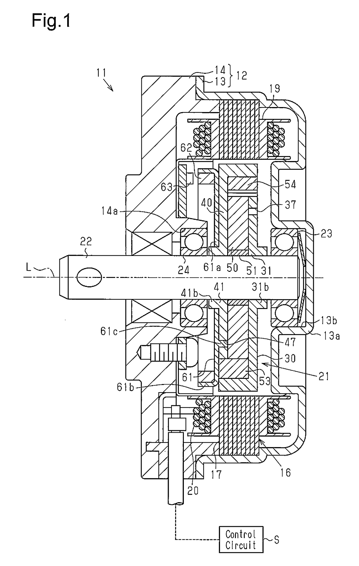
[0033]A first embodiment of a motor will be described below.

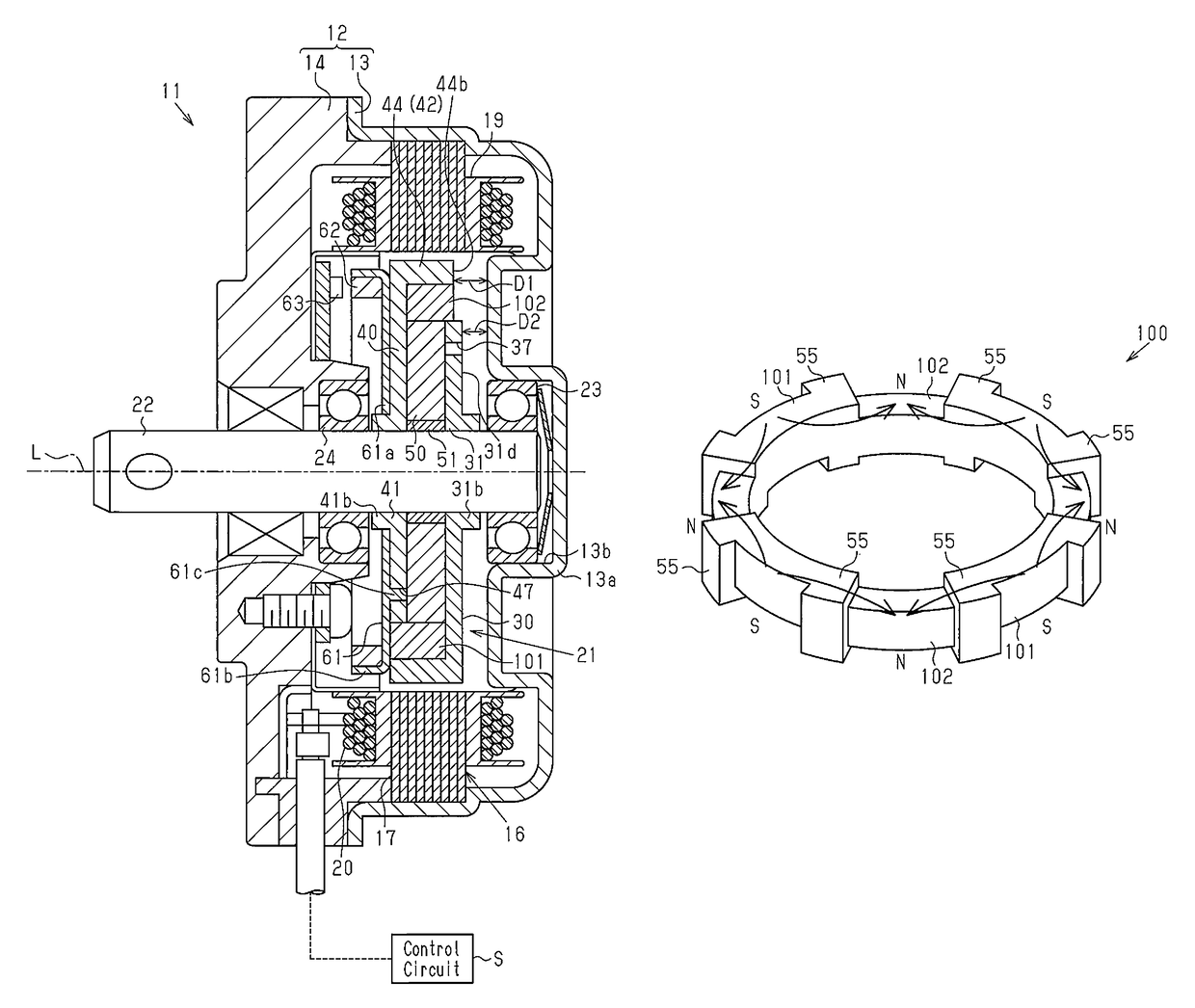
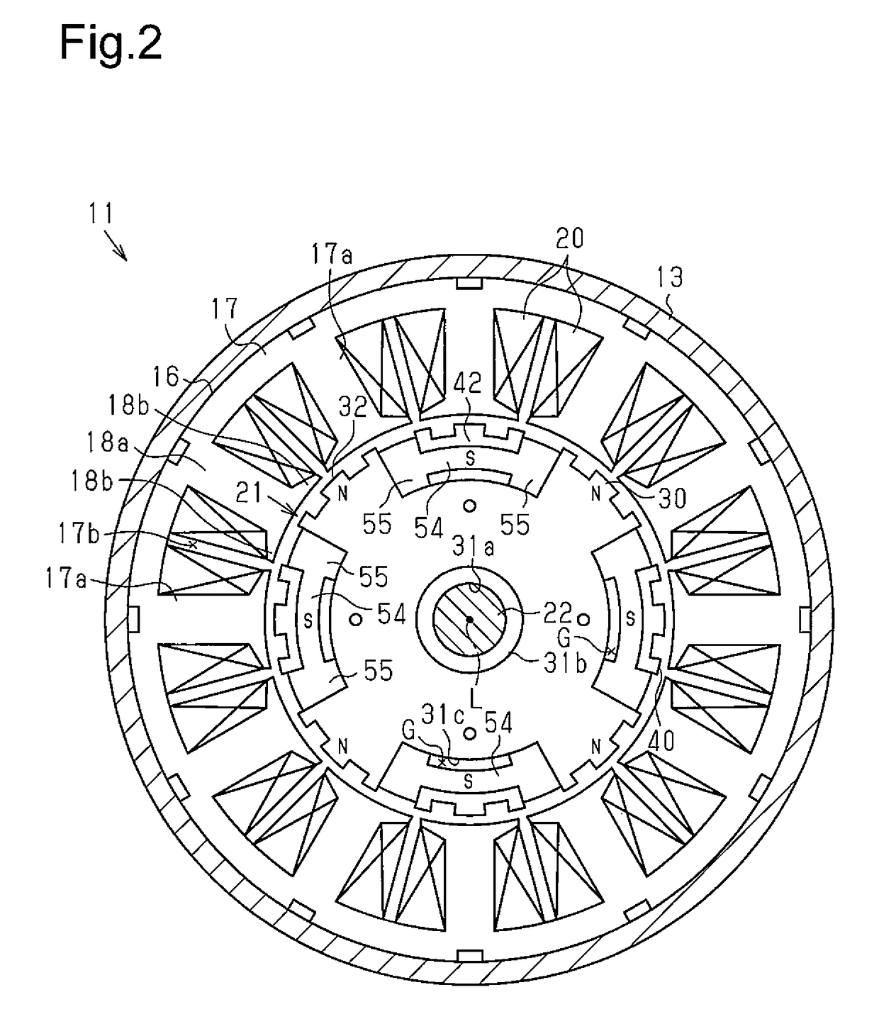
[0034]As illustrated in FIG. 1, a case 12 of a brushless motor 11 serving as a motor has a yoke housing 13 formed having a substantially cylindrical shape with a bottom and an end plate 14 serving as a lid portion for closing an opening of a front side (left side in FIG. 1) of this yoke housing 13. The yoke housing 13 is constituted by a magnetic body (iron, for example), for example. The end plate 14 is constituted by a non-magnetic body (a resin material, for example), for example.

[0035]As illustrated in FIG. 1, a stator 16 is fixed to an inner peripheral surface of the yoke housing 13. The stator 16 is provided with a stator core 17 having a plurality of teeth 17a extending to an inside in the radial direction and a winding 20 wound around the teeth 17a of the stator core 17 through an insulator 19. The stator 16 generates a rotating magnetic field when a driving current is supplied to the winding 20 from an external con...

second embodiment

[0073]Subsequently, a second embodiment of a motor will be described.

[0074]The motor of the second embodiment is different from the first embodiment in a configuration of a rotor, and the stator has the same configuration. Thus, the rotor will be mainly described, and the same reference numerals are given to the other configurations, and a part of or the whole of the explanation will be omitted.

[0075]As illustrated in FIGS. 10 and 11, the rotor 21 of the brushless motor 11 has the rotating shaft 22 and is arranged inside the stator 16. The rotating shaft 22 is a non-magnetic body metal shaft and is supported rotatably by the bearings 23 and 24 supported by the bearing holding portion 13b of the bottom portion 13a of the yoke housing 13 and the bearing holding portion 14a of the end plate 14.

[0076]As illustrated in FIG. 11, the rotor 21 includes the first and second rotor cores 30 and 40, the annular magnet 50 serving as a field magnet interposed between the rotor cores 30 and 40 in ...

third embodiment

[0111]Subsequently, a third embodiment of a motor will be described.

[0112]As illustrated in FIG. 14, a motor case 212 of a brushless motor 211 as a motor has a yoke housing 213 formed having a substantially cylindrical shape with a bottom and an end frame 214 as a lid portion for closing an opening of a front side (left side in FIG. 14) in the axial direction of this yoke housing 213. The yoke housing 213 is constituted by a magnetic body (iron, for example), for example. The end frame 214 is constituted by a non-magnetic body (a resin material, for example), for example.

[0113]As illustrated in FIGS. 14 and 15, a stator 216 is fixed to an inner peripheral surface of the yoke housing 213. The stator 216 is provided with a stator core 217 having a plurality of teeth 217a extending to an inside in the radial direction and a winding 220 wound around the teeth 217a of the stator core 217 through an insulator 219. The stator 216 generates a rotating magnetic field when a driving current i...


PUM


Abstract

A motor includes a stator, a rotor, a case, and back-surface magnet portions. The rotor has a first rotor core, a second rotor core and a field magnet. Each of the first and second rotor cores has a core base and claw-shaped magnetic poles. The field magnet is sandwiched between the first rotor core and the second rotor core and causes the claw-shaped magnetic poles of the first rotor core and the second rotor core to function as different magnetic poles. The back-surface magnet portions include a second and a first back-surface magnet portions respectively provided on the back surfaces of the claw-shaped magnetic poles of the second rotor core and the first rotor core. Size of the second back-surface magnet portion differs from size of the first back-surface magnet portion are different from each other.

Description

RELATED APPLICATIONS[0001]This present application claims priority to Japanese Patent Application No. 2014-083713 filed Apr. 15, 2014, Japanese Patent Application No. 2014-203193 filed Oct. 1, 2014, and Japanese Patent Application No. 2014-213674 filed Oct. 20, 2014 said priority applications being each fully incorporated herein by reference in their entireties.FIELD OF THE INVENTION[0002]The present invention relates to a motor accommodating a stator and a rotor in a case.BACKGROUND OF THE INVENTION[0003]Conventionally, as a rotor used in a motor, a rotor having a Lundell structure with a so-called permanent magnet field disclosed in Japanese Patent Laid-Open Publication No. 2012-115085 and Japanese Utility Model Laid-Open Publication No. 5-43749 is known. Such a rotor includes two rotor cores combined with each other and a field magnet arranged between the two rotor cores. Each of the rotor cores has a plurality of claw-shaped magnetic poles aligned in a peripheral direction. The ...

Claims


Application Information

Patent Timeline
Patent Type & Authority Patents(United States)
IPC IPC(8): H02K1/27H02K1/24H02K21/16H02K19/10
CPCH02K1/243H02K1/2713H02K1/2746H02K21/16H02K19/103
Inventor YAMADA, YOJIMIKAMI, KOJITSUCHIYA, TAKAHIRO
Owner DENSO CORP
Why Eureka
Try Eureka