Electro-cardiograph sensor mat

a sensor mat and electro-cardiograph technology, applied in the field of electro-cardiograph sensor mats, can solve the problems of high risk of skin burns and potential heating at the end of wires, and achieve the effect of ensuring the safety of the mat and the possibility of operating the switch

Active Publication Date: 2017-07-18
KONINKLIJKE PHILIPS ELECTRONICS NV
View PDF10 Cites 0 Cited by
  • Summary
  • Abstract
  • Description
  • Claims
  • Application Information

AI Technical Summary

Benefits of technology

[0012]Embodiments of the invention may have the advantage that the exact location of the electrodes of the sensor mat in relation to the patient anatomy can be obtained by magnetic resonance imaging (MRI). MRI has the advantage that it is very sensitive to soft tissue contrast and thus permits to determine in a highly exact manner the patient anatomy. Further, the advantage of MRI is that radiation occurring in CT is avoided. Further, during interventions performed for example in a combined X-ray and magnetic resonance (MR) interventional suite (XMR) or even MRI only setup, magnetic resonance imaging may be additionally used to visualize ablated structures and then ablation and mapping may be continued, again using the vest. Ablation can be performed for example using patient-specific cardiac radio-frequency ablation.
[0032]In accordance with a further embodiment of the invention, the electric wires are not necessarily segmented but have a resistivity of at least 2 kOhm / m, preferably 5 kOhmm. This has the advantage that potentially present RF resonances are further damped and thus MR image artifacts are further minimized. Nevertheless, this still allows the transmission of the ECG signal. Additionally segmenting the highly resistive wires may be used to further increase safety and / or reduce image artifacts.

Problems solved by technology

This leads to potential heating at the ends of the wires, which means in particular at the electrodes.
However, since the electrodes need to be directly adjacent to the skin, there is a high risk of skin burning due to the heating.

Method used


Image

  • Electro-cardiograph sensor mat
  • Electro-cardiograph sensor mat
  • Electro-cardiograph sensor mat

Examples


Embodiment Construction

[0039]In the following, similar elements are depicted by the same reference numerals.

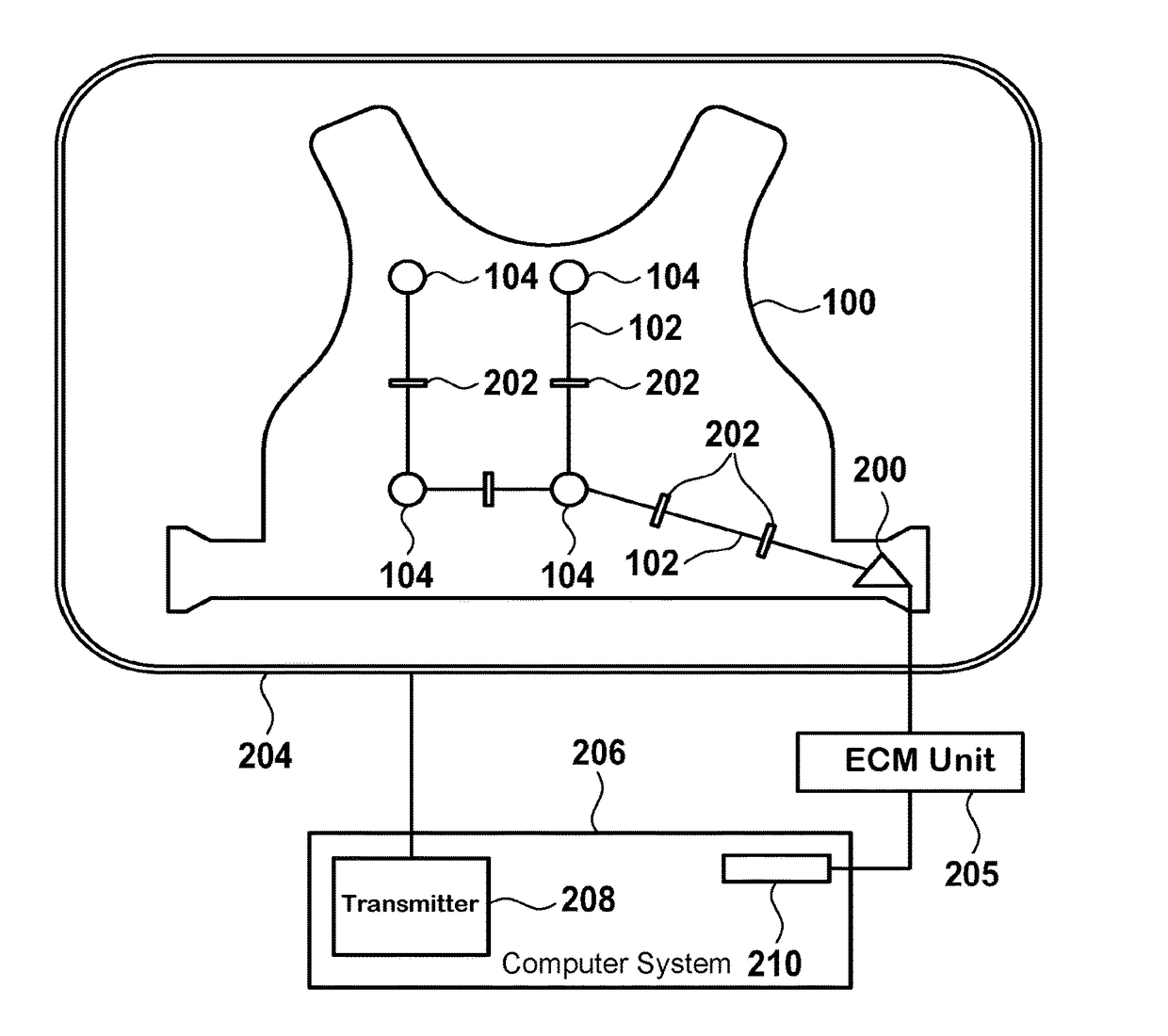
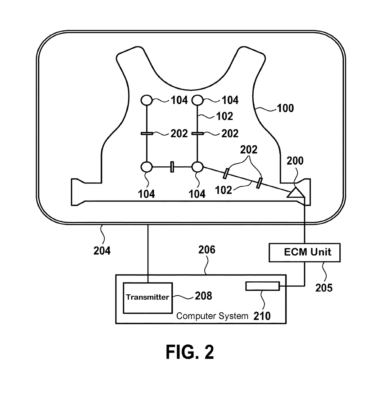
[0040]FIG. 2 shows a schematic of an electro-cardiograph sensor mat 100. The mat comprises a multitude of electrodes 104 for acquiring cardiac signals of a patient. Preferably, the sensor mat is attached to the patient, for example worn by the patient. In this case, preferably the sensor mat is a vest worn by the patient.

[0041]The individual electrodes 104 are connected to a plug 200 of the vest 100. The connection is depicted by electric wires 102. The electric wires 102 are segmented by switches 202, wherein the switches are switchable between a closed state and an open state, wherein in the closed state the electrodes are electrically connected to the plug and wherein in the open state the electrodes are electrically isolated from the plug.

[0042]Further shown in FIG. 2 is an RF antenna 204 of a magnetic resonance imaging system. Typically, such a system comprises super-conducting or resistive mai...


PUM


Abstract

The invention relates to an electrocardiograph sensor mat (100), the mat (100) comprising a multitude of electrodes (104) for acquiring cardiac signals and a plug (200), wherein the electrodes (104) are connected to the plug (200) by electric wires (102), wherein the wires (102) are segmented by switches (202), wherein the switches (202) are switchable between a closed state and an open state, wherein in the closed state the electrodes (104) are electrically connected to the plug (200) and wherein in the open state the electrodes (104) are electrically isolated from the plug (200).

Description

CROSS-REFERENCE TO PRIOR APPLICATIONS[0001]This application is the U.S. National Phase application under 35 U.S.C. §371 of International Application No. PCT / IB2013 / 050021, filed on Jan. 2, 2013, which claims the benefit of U.S. Provisional Patent Application No. 61 / 584,870, filed on Jan. 10, 2012 and European Patent Application No. 12150541.6, filed on Jan. 10, 2012. These applications are hereby incorporated by reference herein.FIELD OF THE INVENTION[0002]The invention relates to an electrode cardiograph sensor mat.BACKGROUND OF THE INVENTION[0003]Heart disease is the number one cause of death in the world. Abnormal electric activity of the heart due to for example cardiac arrhythmia, including atrial fibrillation (AF) and ventricular tachycardia (VT) and congestive heart failure (CHF) are the fastest growing areas for both clinical and industrial development.[0004]Electro-cardiographic mapping (ECM) is a non-invasive technique that provides detailed cardiac electrical activity inf...

Claims


Application Information

Patent Timeline
Patent Type & Authority Patents(United States)
IPC IPC(8): A61B5/0408A61B5/00A61B5/0428A61B5/055A61B5/308
CPCA61B5/6892A61B5/04085A61B5/04288A61B5/6804A61B5/6805A61B5/055A61B5/304A61B5/282
Inventor SMINK, JOUKEWEISS, STEFFENKRUEGER, SASCHA
Owner KONINKLIJKE PHILIPS ELECTRONICS NV
Why Eureka
Try Eureka