Apparatus and method for bearing lubrication in turbine engines

a technology for bearings and turbine engines, applied in the direction of bearing components, pressure lubrication, shafts and bearings, etc., can solve the problems of oil pressure seal failure, shaft, bearing support, bearing and bearing support leakage,

Active Publication Date: 2005-09-15
HONEYWELL INT INC
View PDF7 Cites 55 Cited by
  • Summary
  • Abstract
  • Description
  • Claims
  • Application Information

AI Technical Summary

Benefits of technology

[0015] In a still further aspect of the present invention, a scavenge port comprises a cap having a receptacle configured to mate with a lubricant removal line; a cap base attached to an engine casing; a low-conductivity insulator between the cap base and the engine casing; a conduit termination fitting attached to the outboard end of a scavenge conduit and disposed inside the cap; and a conduit heat shield enclosing the scavenge conduit so as to block radiation from the engine casing.

Problems solved by technology

However, as the turbine components and the inlet conduit expand and contract during normal operating conditions, this configuration produces stress and undesirable movement between the turbine components and the inlet conduit.
This movement may result in leakage between the shaft, the bearing support, the inlet conduit, and the oil supply line.
However, the reference further discloses that, because the operating temperature of the bearing gallery may reach 375° F., use of a conventional o-ring material may result in failure of the oil pressure seal.
This design, however, suffers from the shortcoming in that vibrational forces generated during normal operation cause cracks in the bellows 43 and result in air leakage.

Method used


Image

  • Apparatus and method for bearing lubrication in turbine engines
  • Apparatus and method for bearing lubrication in turbine engines
  • Apparatus and method for bearing lubrication in turbine engines

Examples


Embodiment Construction

[0036] The following detailed description is of the best currently contemplated modes of carrying out the invention. The description is not to be taken in a limiting sense, but is made merely for the purpose of illustrating the general principles of the invention, since the scope of the invention is best defined by the appended claims.

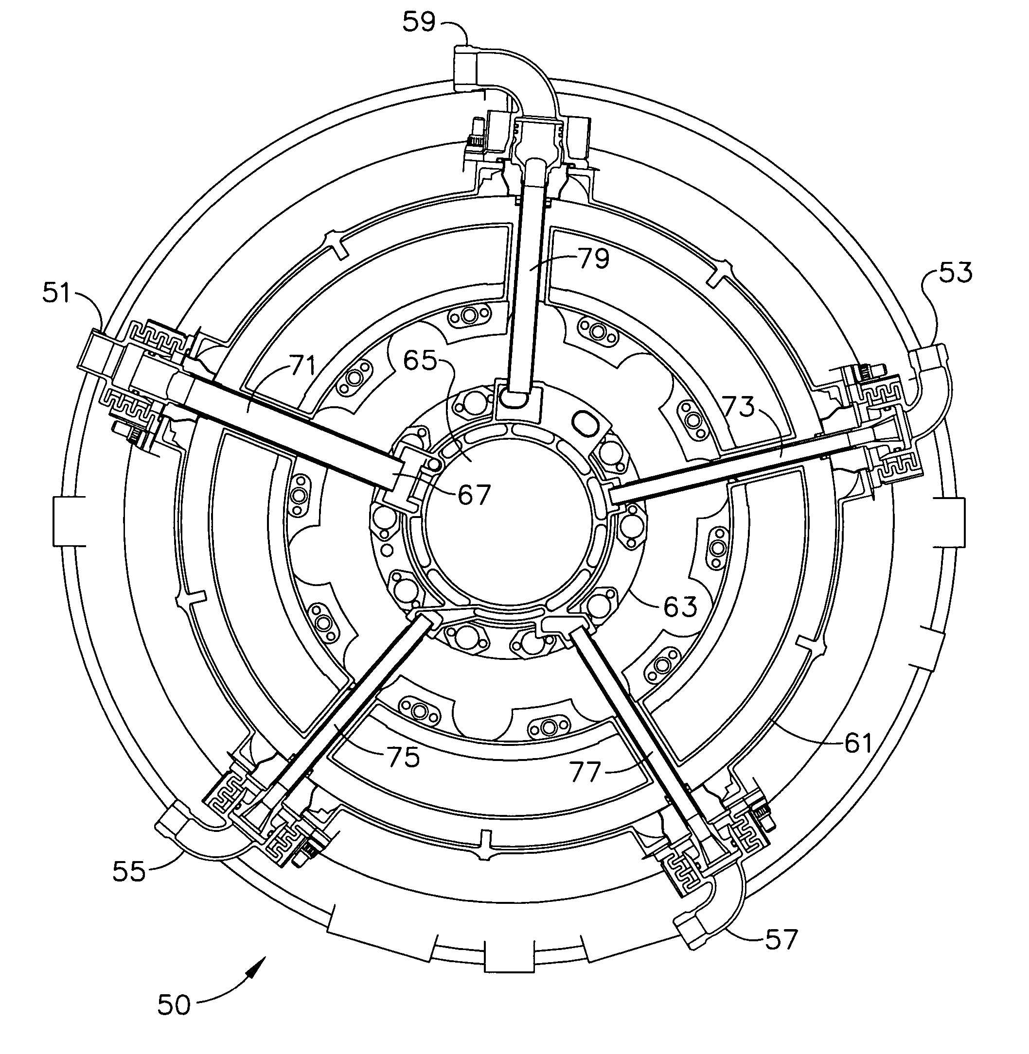
[0037] The present invention is an apparatus and method for providing lubrication to support bearings in a turbine engine wherein the lubrication apparatus includes novel features to reduce equilibrium operating temperatures at all apparatus-to-engine-casing interfaces. Radiation shields may be used to block thermal radiation from the engine casing, and low conductivity gaskets may be disposed between the lubrication apparatus access caps and the engine casing to reduce conductive heat flow from the engine. The lubrication apparatus access caps may have a double-wall construction, with an outside wall being convoluted to provide greater cooling. Heat ...


PUM


Abstract

A lubrication system includes an inlet conduit having an inboard end attached to a bearing support and an outboard end for receiving lubricant. A lubricant inlet assembly is attached to the inlet conduit outboard end and has an inlet cap with a receptacle, an inlet cap body, and a cap base. The inlet receptacle is configured to mate with a lubricant supply line, where the inlet cap body has an outer cap enclosing an inner cap, the outer cap having a convoluted wall. An inlet conduit termination fitting has an outboard fitting section, with an o-ring in a circumferential groove, disposed inside the inlet cap, and an inboard fitting section attached to the inlet conduit outboard end. A cap heat shield encloses the inlet cap and a conduit heat shield is attached to the inlet conduit. The lubricant inlet assembly is mounted to an engine casing with a low-conductivity insulating gasket between the cap base and the engine casing.

Description

GOVERNMENT RIGHTS [0001] This invention was made with Government support under Contract No. DAAH23-02-C-0122 awarded by the United States Army. The Government has certain rights in this invention.BACKGROUND OF THE INVENTION [0002] The present invention generally relates to bearing lubrication and, more specifically, to an improved apparatus and method for providing lubrication to bearing supports in turbine engines. [0003] Shaft-driven machinery, such as gas turbine machinery, typically include a centrally-located shaft mounted in support bearings rotating about an engine axis and housed in an engine casing. Lubrication, in the form of oil, is usually provided to the support bearings by means of an oil supply line provided to the engine casing, with the supply line usually attached to an internal lubricant inlet conduit connected to the bearing support. Scavenge oil may be removed from the bearing support and re-used after cooling and deaerating. A vent assembly may also be provided...

Claims


Application Information

Patent Timeline
Patent Type & Authority Applications(United States)
IPC IPC(8): F01D9/06F01D25/00F01D25/18F01M1/04
CPCF01D25/183F01D9/065F01D9/06F01D25/18F16C33/66
Inventor ZALEWSKI, GEORGE J.ROBINSON, DANIEL J.KYLER, MARKLOPER, DONN
Owner HONEYWELL INT INC
Why Eureka
Try Eureka