Communication Terminal Apparatus And Wireless Transmission Method

a technology of communication terminals and wireless transmission, applied in the field ofcollectors, can solve problems such as unpractical complex systems

Inactive Publication Date: 2007-07-26
BIOSYNERGETICS INC
View PDF73 Cites 62 Cited by
  • Summary
  • Abstract
  • Description
  • Claims
  • Application Information

AI Technical Summary

Benefits of technology

[0005] In another exemplary embodiment, a collector for collecting radiation incident on the collector from at least a first direction comprises a propagation component configured to transmit radiation and having a first end and at least a first refractive index; a buffer component coupled to the propagation component and configured to transmit radiation and having at least a second refractive index, the second refractive index being less than the first refractive index of the propagation component; and a radiation directing component coupled to the buffer component and configured to redirect the incident radiation from the at least first direction along at least a second direction different than the first direction within the buffer component, such that the radiation enters the propagation component and is propagated within the propagation component toward a first end of the propagation component by at least total internal reflection. In one example, the radiation is solar radiation and the buffer component is positioned relative to the propagation component and the radiation directing component, such that the radiation propagating in the propagation component is prevented from interacting with the radiation directing component.

Problems solved by technology

Such requirements result in complex systems which are not practical.

Method used


Image

  • Communication Terminal Apparatus And Wireless Transmission Method
  • Communication Terminal Apparatus And Wireless Transmission Method
  • Communication Terminal Apparatus And Wireless Transmission Method

Examples


Embodiment Construction

[0041] While the invention is susceptible to various modifications and alternative forms, exemplary embodiments thereof have been shown by way of example in the drawings and will herein be described in detail. It should be understood, however, that there is no intent to limit the invention to the particular forms disclosed, but on the contrary, the intention is to cover all modifications, equivalents, and alternatives falling within the spirit and scope of the invention as defined by the appended claims.

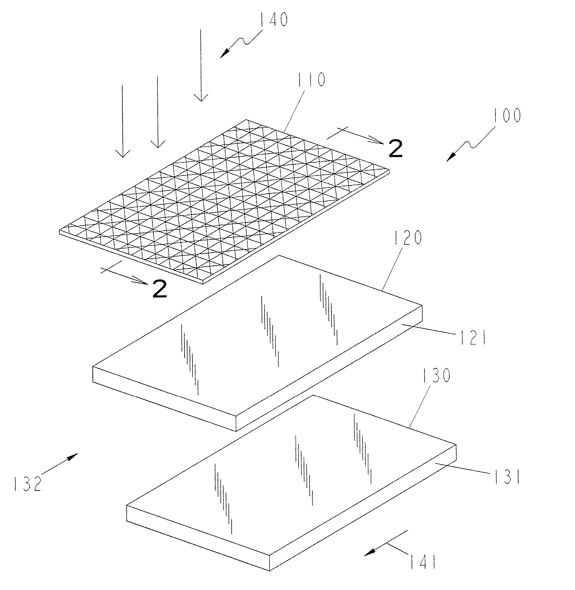
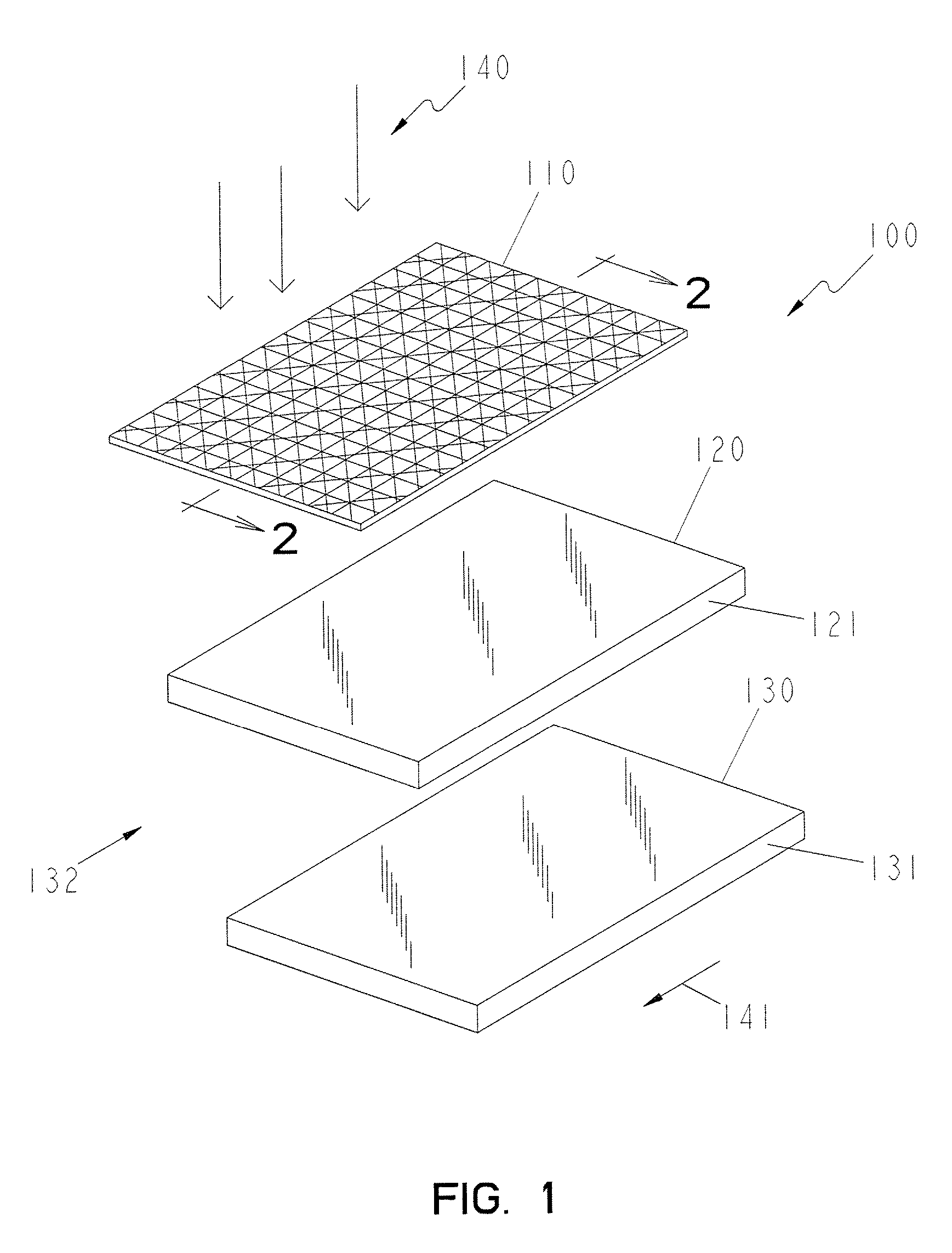
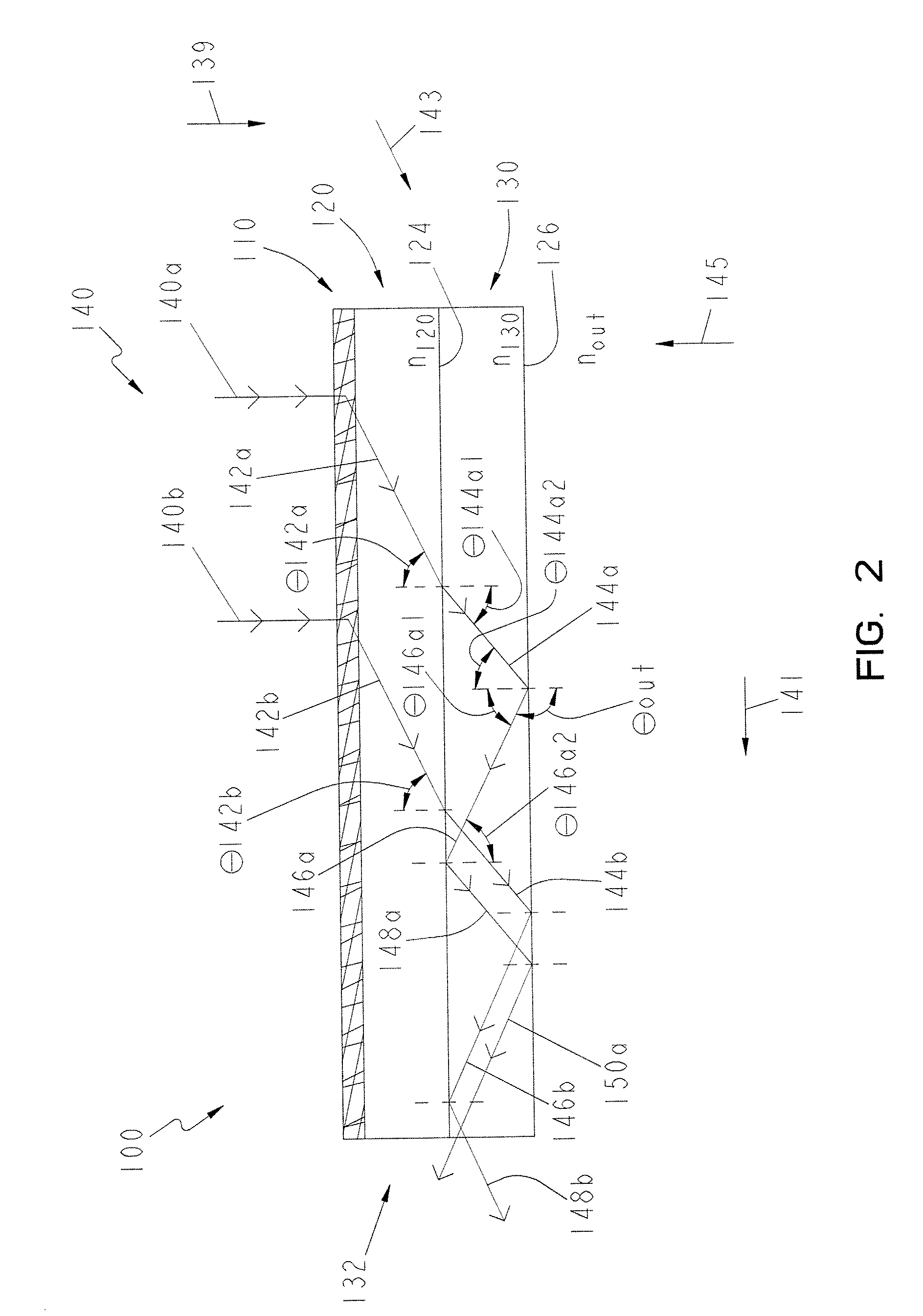
[0042] Referring to FIG. 1, a first embodiment of a radiation or solar collector 100 is shown. Solar collector 100 includes a radiation or light directing component 110, a buffering component 120, and a propagation component 130. As described in detail below, radiation or light directing component 110 is configured to redirect at least a portion of the incident solar radiation 140 on solar collector 100 into propagation component 130, propagation component 130 is configured to colle...


PUM


Abstract

A collector for propagating incident radiation to a remote location. The collector comprises, a light directing component coupled to a buffer component, a first propagation component coupled to the buffer component and configured to transmit the incident radiation into a collector region through one of a plurality of windows, and an optical transport assembly coupled to an end of the collector region and having a second propagation component. Each light directing component is configured to redirect the incident radiation from a first direction to a second direction, and the collector region includes a plurality of regions exhibiting a refractive index value that gradually transitions from about 1.5 to about 2.0. The second propagation component is further configured to retain the incident radiation.

Description

REFERENCE TO RELATED APPLICATIONS [0001] The present application is a continuation-in-part of U.S. patent application Ser. No. 11 / 215,789, filed Aug. 30, 2005, which is a divisional of U.S. patent application Ser. No. 10 / 369,052, filed Feb. 18, 2003, now U.S. Pat. No. 6,957,650, the disclosures of which are hereby expressly incorporated in their entirety by this reference. This patent application also claims the benefit of U.S. Provisional Application No. 60 / 357,705, filed on Feb. 15, 2002, the disclosure of which is hereby expressly incorporated by reference.BACKGROUND AND SUMMARY OF THE INVENTION [0002] The present invention relates to collectors configured to collect electromagnetic radiation and in particular, collectors configured to collect solar radiation and further relates to optical connectors for coupling radiation from a first optical component to a second optical component. [0003] Solar energy collectors have used holographic elements to alter the direction of incident ...

Claims


Application Information

Patent Timeline
Patent Type & Authority Applications(United States)
IPC IPC(8): G01J4/00F24S23/00F24S23/79
CPCY02B10/20G02B6/0035G02B6/0023G01J1/0422G02B6/0028G01J1/04G02B6/26F24J2/067F24J2/06Y02E10/44F24S23/00F24S23/12F24S50/20F24S2025/601Y02E10/47
Inventor NYHART, ELDON H. JR.
Owner BIOSYNERGETICS INC
Why Eureka
Try Eureka