Electromagnetic shielding plate, electromagnetic shielding structure, and entertainment system

Inactive Publication Date: 2005-08-16
SONY COMPUTER ENTERTAINMENT INC
View PDF24 Cites 58 Cited by
  • Summary
  • Abstract
  • Description
  • Claims
  • Application Information

AI Technical Summary

Benefits of technology

[0006]The shielding structure described above can ideally restrain electromagnetic radiation to the exterior of the electromagnetic equipment. However, in actually, there is a case where restraining effect for electromagnetic radiation is not exerted satisfactorily. In other words, product-to-product variations in performance of electromagnetic radiation are found. According to the analysis carried out by the inventor of the present invention, it was found that such variations are caused by

Problems solved by technology

However, in actually, there is a case where restraining effect for electromagnetic radiation is not exerted satisfactorily.
Consequently, sufficient shielding is not performed.
However, in this method, it is necessary to solder all around the circumfe

Method used


Image

  • Electromagnetic shielding plate, electromagnetic shielding structure, and entertainment system
  • Electromagnetic shielding plate, electromagnetic shielding structure, and entertainment system
  • Electromagnetic shielding plate, electromagnetic shielding structure, and entertainment system

Examples


second embodiment

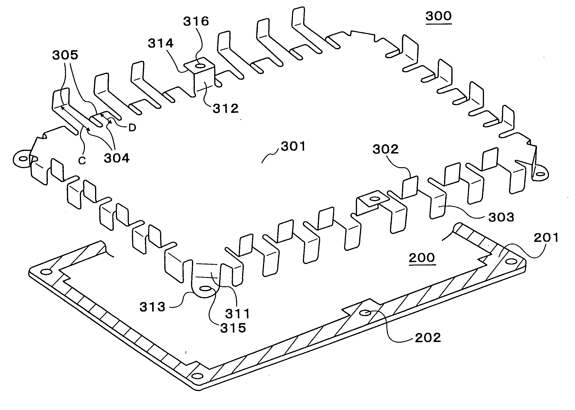
[0034]FIG. 5 and FIG. 6 show a shielding structure of the present invention. The shielding structure according to the present embodiment comprises, as shown in FIG. 5 and FIG. 6, printed boards 200, 250 (the printed board 250 is not shown in FIG. 5), and a shielding plate 300. In the example shown in FIG. 5 and FIG. 6, the state where the shielding plate is mounted between two printed boards is shown.

[0035]The shielding plate 300 according to the present embodiment is formed of a conductive material having resiliency, as is the shielding plate 100 of the first embodiment. The shielding plate 300 comprises a plate portion 301, connecting strips 302, 303, and supporting portions 311, 312. The connecting strips 302, 303 are provided at a plurality of locations along the edge of the plate portion 301, as in the case of the first embodiment. The plurality of connecting strips comprises the first connecting strips 301 and the second connecting strips 303. In other words, the tips of the f...

first embodiment

[0036]The supporting portions 311, 312 are also provided with the first supporting portion 311 and the second supporting portion 312. On the tips of the respective supporting portions 311, 312, as in the first embodiment, there are provided foot portions 313, 314. The foot portions 313, 314 are provided with the through holes 315, 316. The shielding plate 300 is fixed to the lower printed board 200 in the figure via the through hole 315, and to the upper printed board 250 in the figure via the through hole 316.

[0037]As in the first embodiment, the imaginary plane in which the tips of the connecting strips 305, 307 are aligned is located outside of the imaginary plane in which the tips of the supporting portions 311 and 312 are aligned. Therefore, when the printed boards 200 and 250 are fixed on and under the shielding plate 300, the first connecting strips 302 are brought into press contact with the ground pattern 201 of the lower printed board 200, and the second connecting strips ...

third embodiment

[0041]An entertainment system employing a shielding structure will be explained referring to a figure as the present invention. In this embodiment, a structure having a shielding plate on a part of a surface of the printed board will be shown as an example.

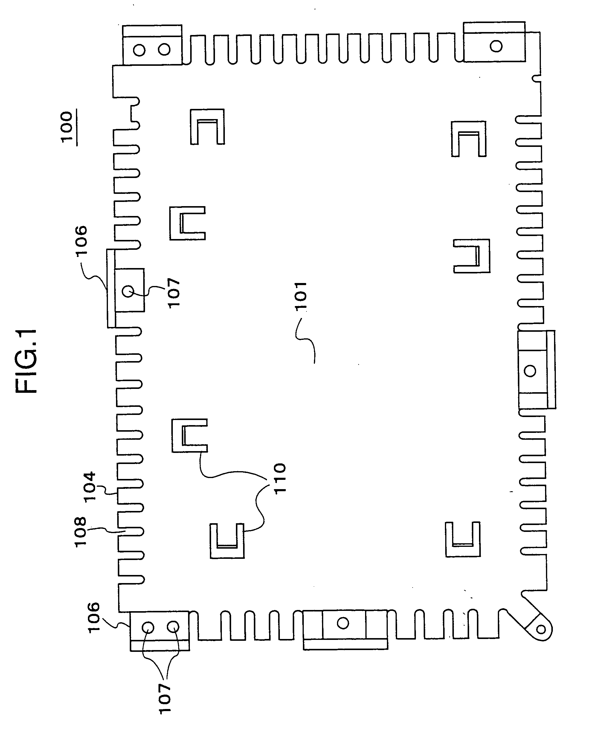
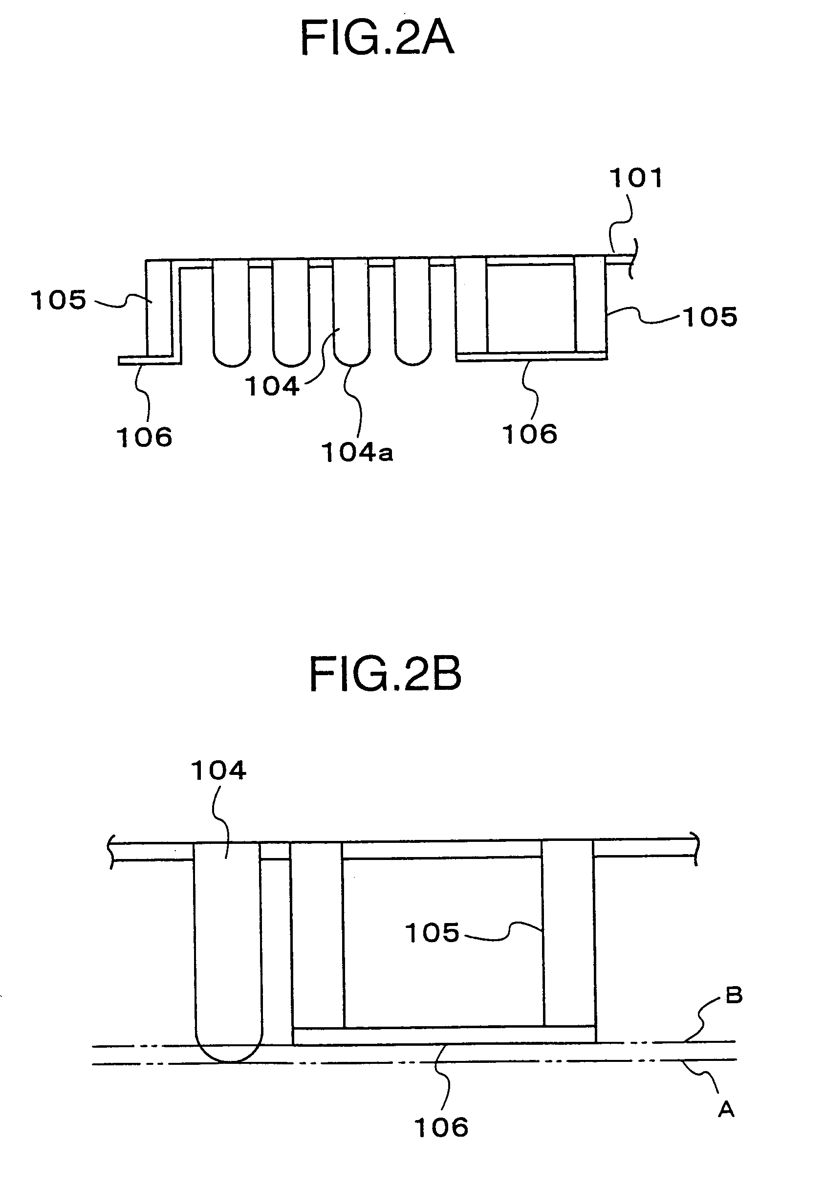
[0042]The entertainment system 500 shown in FIG. 7 comprises at least an enclosure 505, a main control circuit substrate 510, a shielding plate 100, a pipe-shaped heat sink 530, a rectangular heat sink 540, a switch inlet unit 550, an electric power supply unit 560, and a memory card inserting portion 570. The main control circuit substrate 510 is provided with a circuit element including a central processing unit 511 mounted thereon. In this entertainment system 500, the main control circuit substrate 510 that generates the electronic wave most and the shielding plate 100 constitute the shielding structure.

[0043]A plate portion 121 of the shielding plate 100 is provided with a through hole 122, through which the rectangular heat ...


PUM


Abstract

An electromagnetic shielding plate having high shielding effect is provided.
The electromagnetic shielding plate is formed of a conductive plate having elasticity and is provided on the edge thereof with a connecting strip bent in such a manner that the tip thereof projects from the surface of the plate, and with a supporting portion. When the electromagnetic shielding plate and the printed substrate are connected, it is ensured that the ground pattern 201 of the printed board 200 and the connecting strip are brought into contact with respect to each other, thereby a high shielding effect can be obtained.

Description

[0001]This invention claims a priority based on Japanese Patent Application No. 11-257791 filed on Sep. 10, 1999, the entire contents of which are incorporated herein by reference for all purposes.BACKGROUND OF THE INVENTION[0002]The present invention relates to an electromagnetic shielding plate, an electromagnetic shielding structure, and an entertainment system having the electromagnetic shielding structure.[0003]In electronic equipment, there are cases where electromagnetic waves are generated resulting from actions of internal equipment and are radiated out to the exterior of equipment. In recent years, it is strongly desired to minimize radiation of unnecessary electromagnetic wave in terms of electronic equipment. Therefore, in electronic equipment, shielding is carried out in such a manner that the enclosure itself is shielded, or the device mounted surface of the printed board is shielded by covering it with a box-shaped member formed of a metal.[0004]For example, in case w...

Claims


Application Information

Patent Timeline
IPC IPC(8): H05K9/00
CPCH05K9/0026H05K9/0039H05K9/00
Inventor HAMA, TOSHIKATSUMURASAWA, OSAMU
Owner SONY COMPUTER ENTERTAINMENT INC
Why Eureka
Try Eureka