Electro-cardiograph sensor mat

a sensor mat and electro-cardiograph technology, applied in the field of electro-cardiograph sensor mats, can solve the problems of high risk of skin burns and potential heating at the end of wires, and achieve the effect of ensuring the safety of the mat and the possibility of operating the switch

Active Publication Date: 2014-12-11
KONINKLIJKE PHILIPS ELECTRONICS NV
View PDF0 Cites 3 Cited by
  • Summary
  • Abstract
  • Description
  • Claims
  • Application Information

AI Technical Summary

Benefits of technology

[0022]In accordance with an embodiment of the invention, the switches are mechanical switches. For example, the switches are operable by pressurized gas, wherein the mat comprises an interface for receiving a connector supplying the gas and for providing a gas connection with the switches. This may have the advantage that an MR safe possibility of operating the switches can be provided. No further electrical connections for operating of the switches are required, which may further disturb the MR image acquisition process.
[0023]In accordance with an embodiment of the invention, the switches are adapted for being switched from the open state to the closed state upon reception of the gas in a pressurized state. This may have the advantage that MR safety in the passive, i.e. in the non-pressurized state, can be ensured.
[0024]In accordance with a further embodiment of the invention, the switches are adapted for automatically switching from the closed state to the open state upon a release of the pressurized gas. Again, this also may have the advantage that MR safety of the mat is ensured. Further, this may permit to reuse the electro-cardiograph sensor mat a multitude of times due to the reversibility of the switching process.
[0025]In accordance with a further embodiment of the invention, the mechanical switches comprises removable conducting elements, wherein the elements are fixed to a removable layer, wherein the switches are adapted for being switched from the closed state to the open state upon movement of the layer. In this alternative embodiment MR safety can be ensured by simply removing the layer comprising the removable conducting elements. Preferably, such a layer should be marked in a clearly visual manner such that an operator of the MR apparatus is easily able to check if the mat is in its MR safety state or not. Preferably, the vest and the layer should be marked for example by colors in such a manner that the MR safe state and the MR non-safe state are easily distinguishable.

Problems solved by technology

This leads to potential heating at the ends of the wires, which means in particular at the electrodes.
However, since the electrodes need to be directly adjacent to the skin, there is a high risk of skin burning due to the heating.

Method used


Image

  • Electro-cardiograph sensor mat
  • Electro-cardiograph sensor mat
  • Electro-cardiograph sensor mat

Examples


Embodiment Construction

[0038]In the following, similar elements are depicted by the same reference numerals.

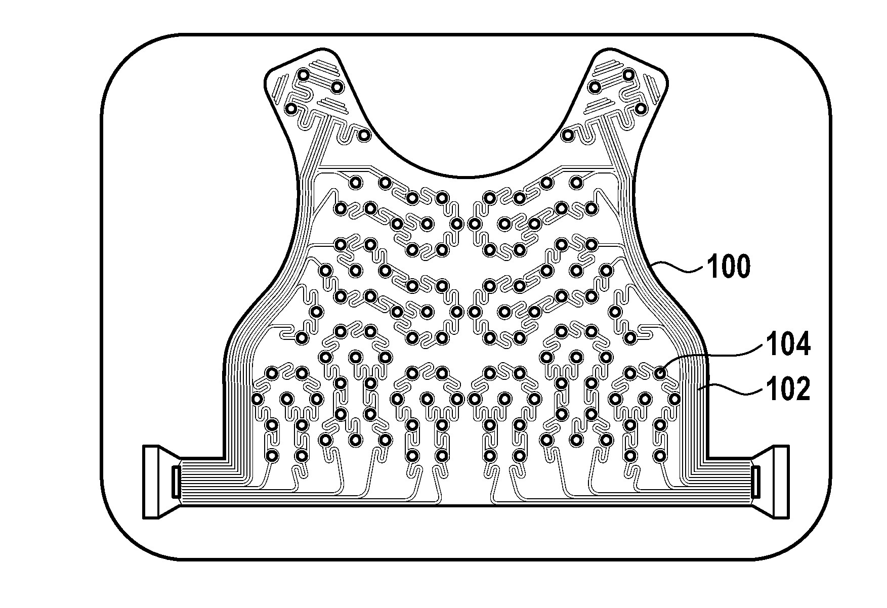
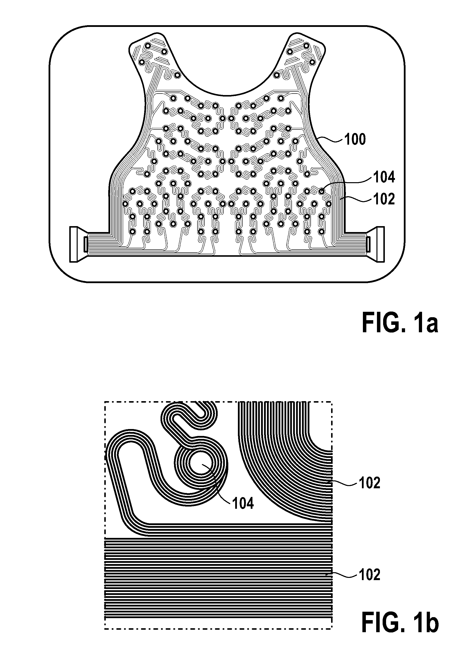
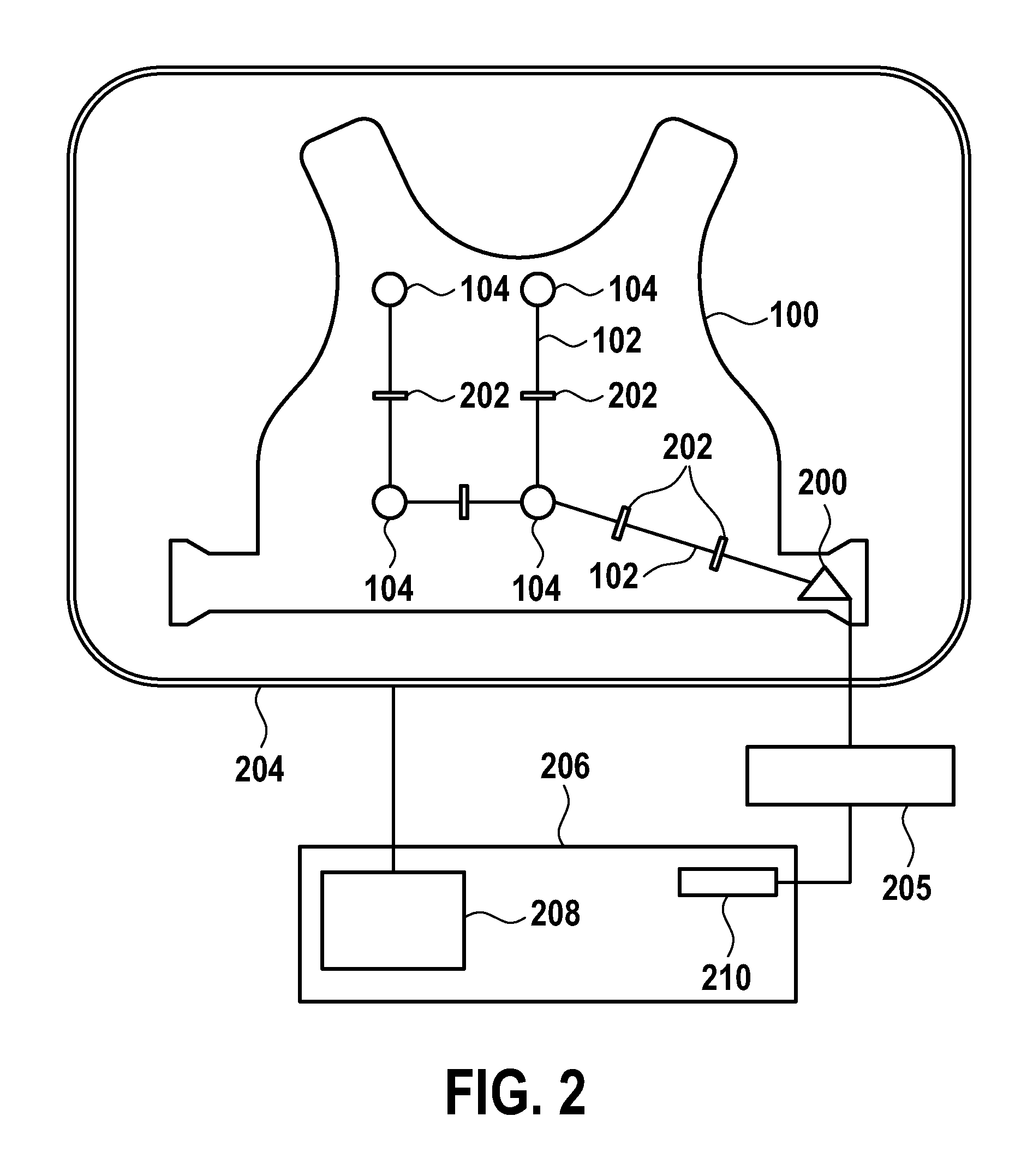
[0039]FIG. 2 shows a schematic of an electro-cardiograph sensor mat 100. The mat comprises a multitude of electrodes 104 for acquiring cardiac signals of a patient. Preferably, the sensor mat is attached to the patient, for example worn by the patient. In this case, preferably the sensor mat is a vest worn by the patient.

[0040]The individual electrodes 104 are connected to a plug 200 of the vest 100. The connection is depicted by electric wires 102. The electric wires 102 are segmented by switches 202, wherein the switches are switchable between a closed state and an open state, wherein in the closed state the electrodes are electrically connected to the plug and wherein in the open state the electrodes are electrically isolated from the plug.

[0041]Further shown in FIG. 2 is an RF antenna 204 of a magnetic resonance imaging system. Typically, such a system comprises super-conducting or resistive mai...


PUM


Abstract

The invention relates to an electrocardiograph sensor mat (100), the mat (100) comprising a multitude of electrodes (104) for acquiring cardiac signals and a plug (200), wherein the electrodes (104) are connected to the plug (200) by electric wires (102), wherein the wires (102) are segmented by switches (202), wherein the switches (202) are switchable between a closed state and an open state, wherein in the closed state the electrodes (104) are electrically connected to the plug (200) and wherein in the open state the electrodes (104) are electrically isolated from the plug (200).

Description

FIELD OF THE INVENTION[0001]The invention relates to an electrode cardiograph sensor mat.BACKGROUND OF THE INVENTION[0002]Heart disease is the number one cause of death in the world. Abnormal electric activity of the heart due to for example cardiac arrhythmia, including atrial fibrillation (AF) and ventricular tachycardia (VT) and congestive heart failure (CHF) are the fastest growing areas for both clinical and industrial development.[0003]Electro-cardiographic mapping (ECM) is a non-invasive technique that provides detailed cardiac electrical activity information for the entire heart for each heartbeat by combining body surface electrical data acquired from a large number of surface electrodes with detailed three-dimensional anatomical data obtained from for example computer tomography (CT). It thus has the potential to deliver detailed electrophysiological information, which otherwise can only be measured with cardiac catheters in invasive electrophysiologic procedures. Addition...

Claims


Application Information

Patent Timeline
Patent Type & Authority Applications(United States)
IPC IPC(8): A61B5/00A61B5/0408A61B5/308
CPCA61B5/6892A61B5/7203A61B5/6805A61B5/0408A61B5/055A61B5/304A61B5/282A61B5/6804
Inventor SMINK, JOUKEWEISS, STEFFENKRUEGER, SASCHA
Owner KONINKLIJKE PHILIPS ELECTRONICS NV
Why Eureka
Try Eureka