Drill bit with self-adjusting pads

a drill bit and self-adjusting technology, applied in the field of drill bits and systems, can solve the problems of excessive fluctuations or vibration (lateral or torsional) in the drill bit, and achieve the effect of reducing or increasing the difficulty of drilling

Active Publication Date: 2017-07-18
BAKER HUGHES HLDG LLC
View PDF28 Cites 22 Cited by
  • Summary
  • Abstract
  • Description
  • Claims
  • Application Information

AI Technical Summary

Benefits of technology

The patent describes a drill bit with a rate control device that can adjust the speed at which the bit penetrates the wellbore. The device includes a piston, biasing member, and fluid chamber, and can retract the pad when not in use. The drill bit can also be rotated to hide the pad when not in use. This allows for smoother drilling and reduces the chance of damage to the wellbore. The technical effects of this invention are improved control and efficiency in drilling wellbores.

Problems solved by technology

When drilling progresses from a soft formation, such as sand, to a hard formation, such as shale, or vice versa, the rate of penetration (ROP) of the drill changes and can cause (decreases or increases) excessive fluctuations or vibration (lateral or torsional) in the drill bit.

Method used


Image

  • Drill bit with self-adjusting pads
  • Drill bit with self-adjusting pads
  • Drill bit with self-adjusting pads

Examples


Embodiment Construction

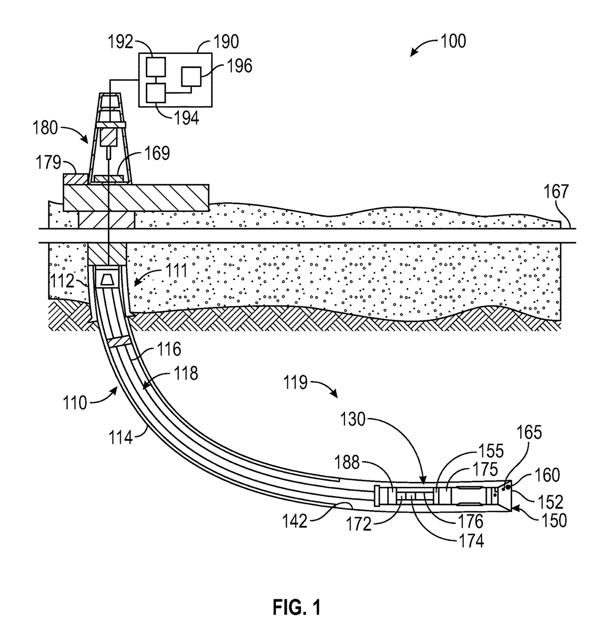
[0029]FIG. 1 is a schematic diagram of an exemplary drilling system 100 that may utilize drill bits made according to the disclosure herein. FIG. 1 shows a wellbore 110 having an upper section 111 with a casing 112 installed therein and a lower section 114 being drilled with a drill string 118. The drill string 118 is shown to include a tubular member 116 with a BHA 130 attached at its bottom end. The tubular member 116 may be made up by joining drill pipe sections or it may be a coiled-tubing. A drill bit 150 is shown attached to the bottom end of the BHA 130 for disintegrating the rock formation 119 to drill the wellbore 110 of a selected diameter.

[0030]Drill string 118 is shown conveyed into the wellbore 110 from a rig 180 at the surface 167. The exemplary rig 180 shown is a land rig for ease of explanation. The apparatus and methods disclosed herein may also be utilized with an offshore rig used for drilling wellbores under water. A rotary table 169 or a top drive (not shown) co...


PUM


Abstract

A drill bit includes a bit body; a pad associated with the bit body; a rate control device coupled to the pad that extends from a bit surface at a first rate and retracts from an extended position to a retracted position at a second rate in response to external force applied onto the pad. The rate control device includes a piston for applying a force on the pad; a biasing member that applies a force on the piston to extend the pad at the first rate; a fluid chamber associated with the piston; and a pressure management device for controlling a fluid pressure within the fluid chamber.

Description

CROSS-REFERENCE TO RELATED APPLICATIONS[0001]This patent application is a Continuation-In-Part Application of U.S. Non-Provisional patent application Ser. No. 13 / 864,926, filed Apr. 17, 2013 which is incorporated herein by reference in its entirety.BACKGROUND[0002]Field of the Disclosure[0003]This disclosure relates generally to drill bits and systems that utilize same for drilling wellbores.[0004]Background of the Art[0005]Oil wells (also referred to as “wellbores” or “boreholes”) are drilled with a drill string that includes a tubular member having a drilling assembly (also referred to as the “bottomhole assembly” or “BHA”). The BHA typically includes devices and sensors that provide information relating to a variety of parameters relating to the drilling operations (“drilling parameters”), behavior of the BHA (“BHA parameters”) and parameters relating to the formation surrounding the wellbore (“formation parameters”). A drill bit attached to the bottom end of the BHA is rotated b...

Claims


Application Information

Patent Timeline
Patent Type & Authority Patents(United States)
IPC IPC(8): E21B10/62E21B10/54E21B10/42E21B3/00
CPCE21B10/62E21B3/00E21B10/42E21B10/54E21B2010/622E21B3/022E21B3/04E21B10/627
Inventor JAIN, JAYESH R.BAXTER, BENJAMINVEMPATI, CHAITANYARADFORD, STEVENRICKS, GREGORY L.BILEN, MIGUELSTIBBE, HOLGERPETERS, VOLKER
Owner BAKER HUGHES HLDG LLC
Why Eureka
Try Eureka