
Diagnostic apparatus and method for an evaporative control system including an integrated pressure management apparatus

Inactive Publication Date: 2005-08-23
SIEMENS VDO AUTOMOTIVE CORP
View PDF85 Cites 21 Cited by
  • Summary
  • Abstract
  • Description
  • Claims
  • Application Information

AI Technical Summary

Problems solved by technology

However, if the evaporative system has a large enough leak, the evaporative system will not maintain switch activation.

Method used


Image

  • Diagnostic apparatus and method for an evaporative control system including an integrated pressure management apparatus
  • Diagnostic apparatus and method for an evaporative control system including an integrated pressure management apparatus
  • Diagnostic apparatus and method for an evaporative control system including an integrated pressure management apparatus

Examples


Embodiment Construction

[0010]As it is used herein, “pressure” is measured relative to the ambient atmospheric pressure. Thus, positive pressure refers to pressure greater than the ambient atmospheric pressure and negative pressure, or “vacuum,” refers to pressure less than the ambient atmospheric pressure.

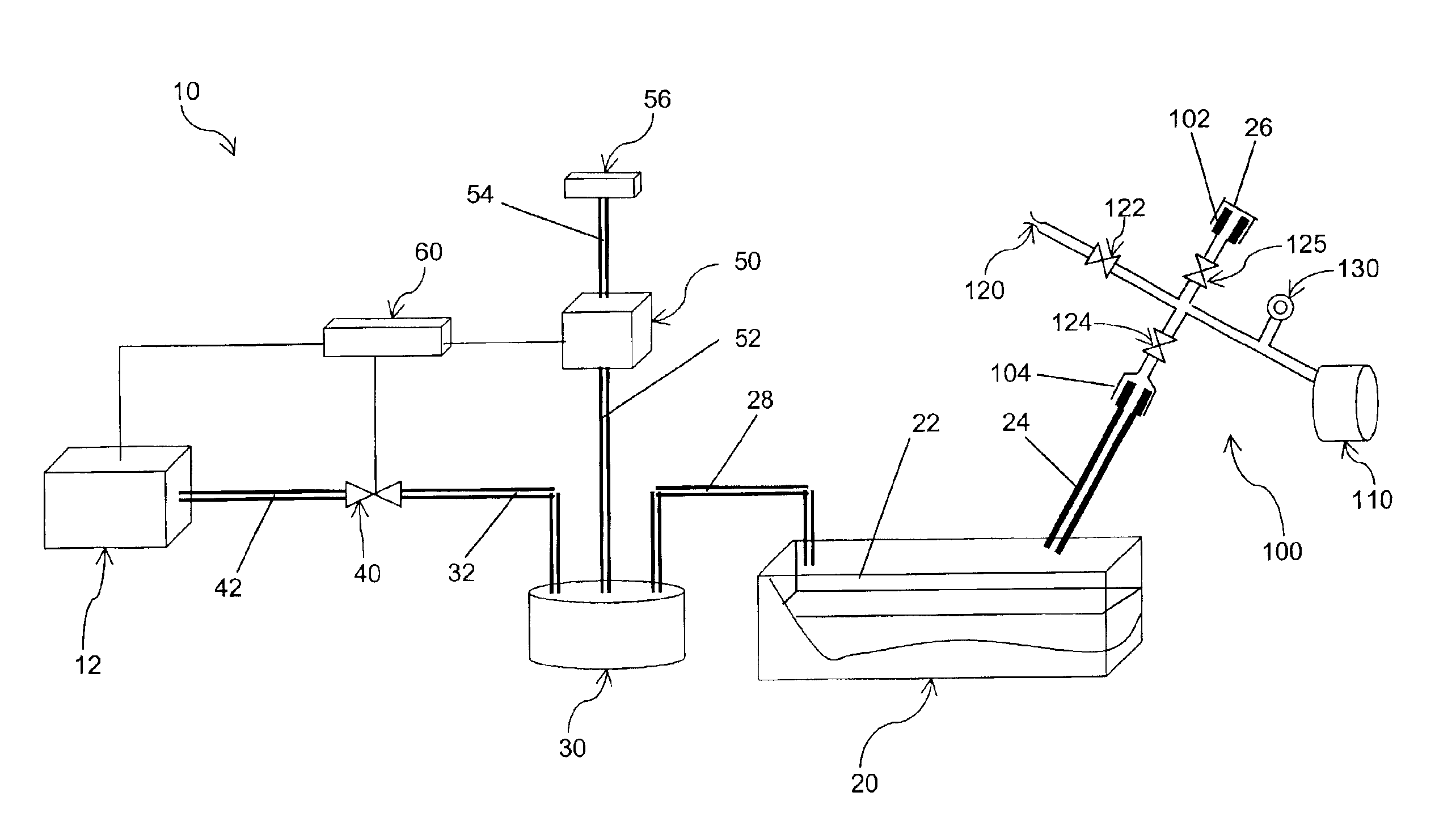
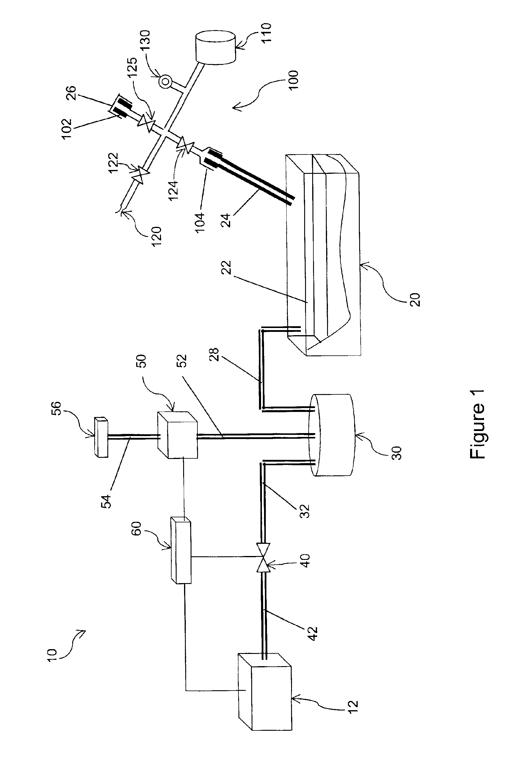
[0011]Referring to FIG. 1, an evaporative control system 10 for an internal combustion engine 12 includes a fuel tank 20, a charcoal canister 30, a purge valve 40, and an IPMA 50.

[0012]The fuel tank 20 contains volatile liquid fuel and fuel vapors in a headspace 22 above the surface of the liquid fuel. A filler 24 that is normally occluded by a cap 26 provides access to the fuel tank 20 during refueling. A first conduit 28 provides fluid communication between the headspace 22 and the charcoal canister 30.

[0013]In a conventional manner, the charcoal canister 30 collects fuel vapors from the beadspace 22. A second conduit 32 provides fluid communication from the charcoal canister 30 to the purge valve 40, ...


PUM


Abstract

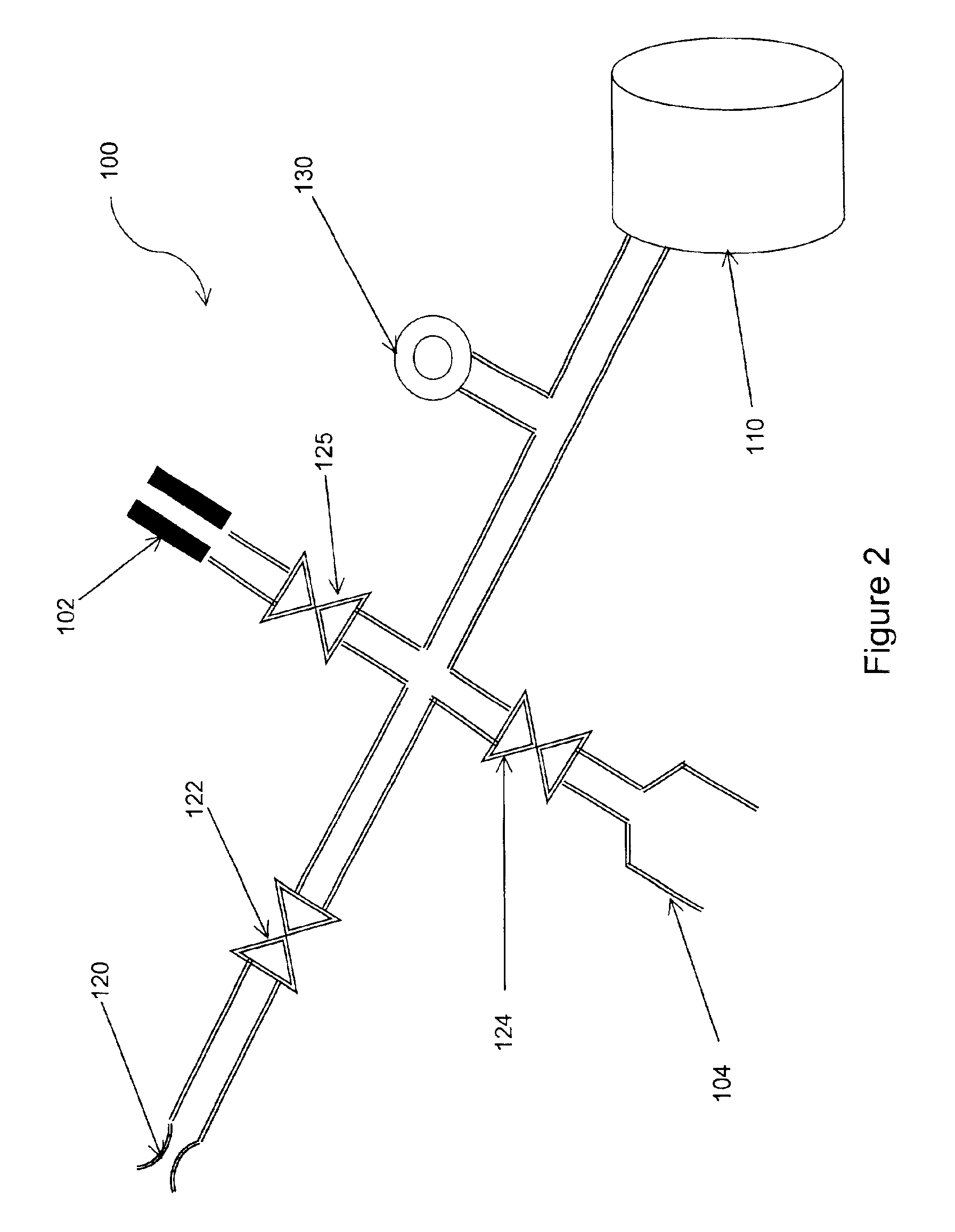
A diagnostic appartus and method for a fuel system that supplies fuel to an internal combustion engine. The fuel system includes a fuel tank that has a headspace and a filler occluded by a removable cap, a charcoal canister in fluid communication with the headspace, and an integrated pressure management apparatus. The integrated pressure management apparatus has a pressure operable device and a switch that signals displacement of the pressure operable device in response to negative pressure at a first pressure level in the charcoal canister. The diagnostic apparatus comprises a pressure source, a first fitting adapted to be occluded by the removable cap, a second fitting adapted to sealingly engage the filler, an orifice in fluid communication with the pressure source, with the first fitting, and with the second fitting, and a first valve controlling the fluid communication with the orifice. The first fitting is in fluid communication with the pressure source, and the second fitting is in fluid communication with the pressure source and with the first fitting.

Description

FIELD OF THE INVENTION[0001]This disclosure generally relates to an apparatus and method for diagnosing a fuel system of an internal combustion engine. In particular, this disclosure is directed to a diagnostic apparatus and method for servicing a fuel system including an integrated pressure management apparatus (IPMA).BACKGROUND OF THE INVENTION[0002]A conventional evaporative control system collects in a charcoal canister the fuel vapor that escapes from a fuel tank. If there is a leak in the fuel tank, canister, or any other component of the evaporative control system, some fuel vapor could escape through the leak into the atmosphere instead of being collected in the canister. Thus, it is desirable to detect leaks.[0003]Leak detection for an evaporative control system is one of several functions that are performed by the IPMA that is disclosed in U.S. patent application Ser. No. 09 / 542,052, filed Mar. 31, 2000, and which is incorporated by reference herein in its entirety. Briefl...

Claims


Application Information

Patent Timeline
IPC IPC(8): F02M25/08
CPCF02M25/0818
Inventor WELDON, CRAIG
Owner SIEMENS VDO AUTOMOTIVE CORP
Learn More