Fixing apparatus and image forming apparatus

a technology of fixing belts and fixing plates, which is applied in the direction of electrographic process equipment, instruments, optics, etc., can solve the problems of restricting the temperature rise of the fixing belts, and achieve the effect of improving the temperature rise performan

Active Publication Date: 2017-07-18
HEWLETT PACKARD DEV CO LP
View PDF20 Cites 0 Cited by
  • Summary
  • Abstract
  • Description
  • Claims
  • Application Information

AI Technical Summary

Benefits of technology

[0021]According to an embodiment, temperature rise performance may be improved.
[0022]According to an embodiment, temperature uniformity of a rotor may be secured.

Problems solved by technology

Therefore, the excessive temperature rise in the fixing belt is restricted.

Method used


Image

  • Fixing apparatus and image forming apparatus
  • Fixing apparatus and image forming apparatus
  • Fixing apparatus and image forming apparatus

Examples


first embodiment

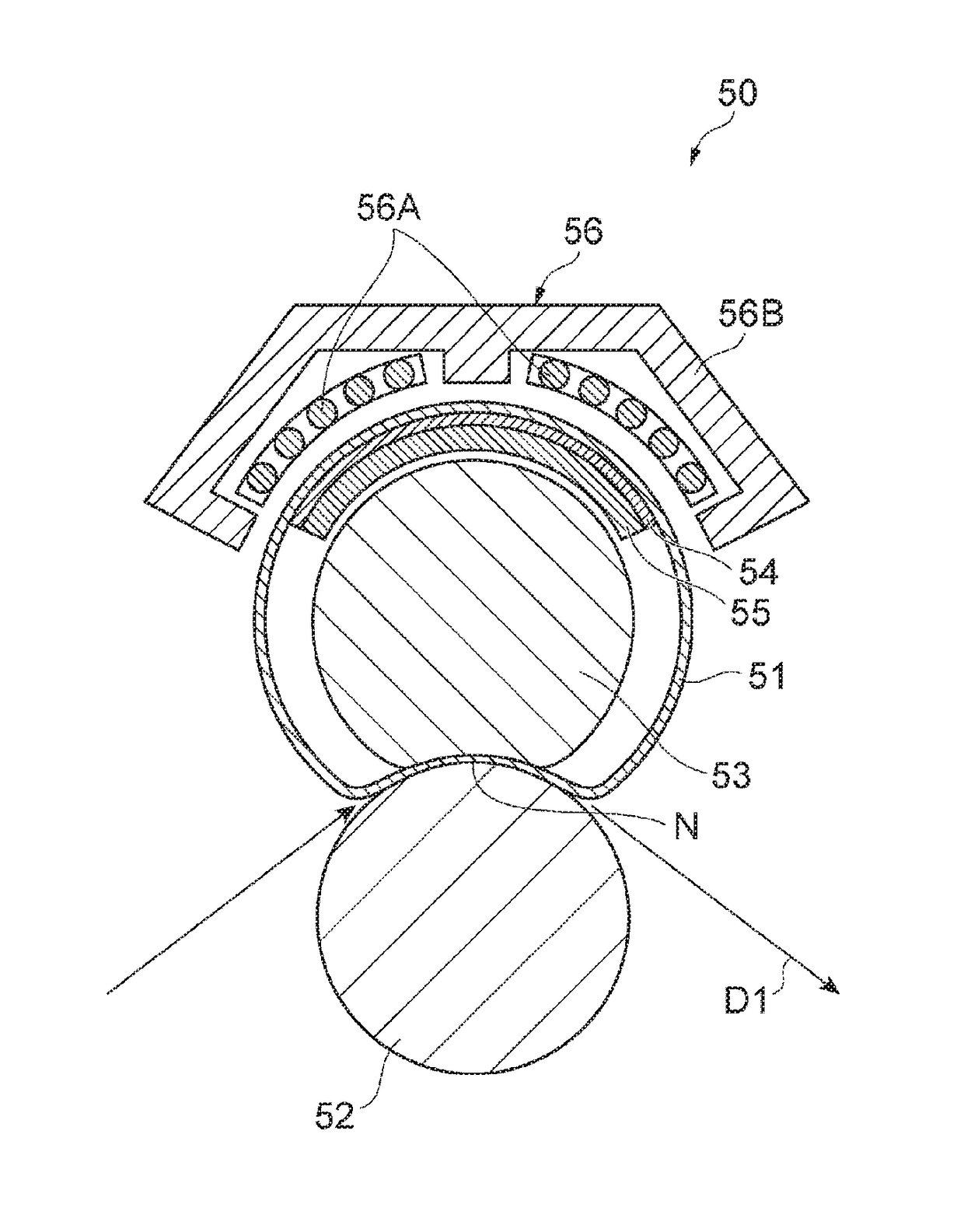
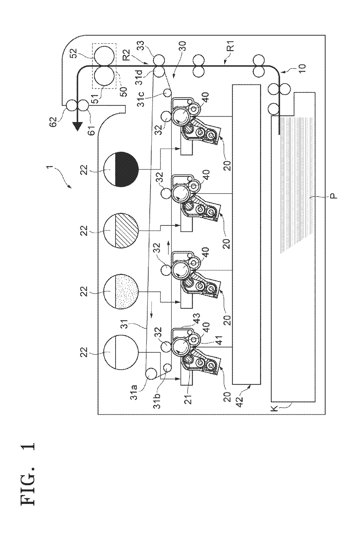
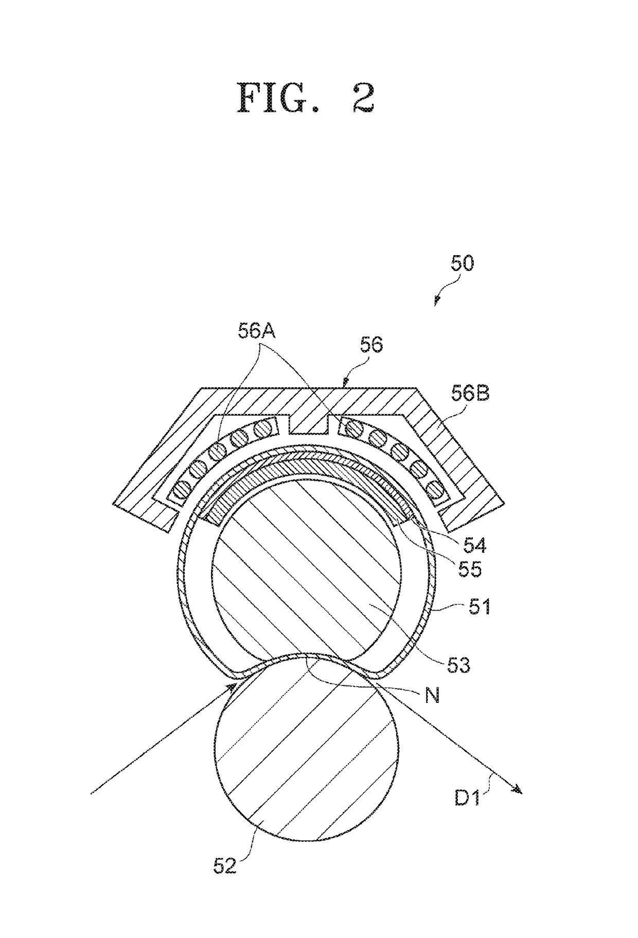
[0034]An image forming apparatus 1 according to a first embodiment produces a color image by using various colors such as magenta, yellow, cyan, and black. As shown in FIG. 1, the image forming apparatus 1 includes a recording medium transport unit 10 for transporting paper P, a developing device 20 for developing an electrostatic latent image, a transfer unit 30 for secondarily transferring a toner image on the paper P, a photoreceptor drum 40 that is an electrostatic latent image carrier for forming an image on an outer circumference surface of the photoreceptor drum 40, and a fixing apparatus 50 for fixing the toner image on the paper P.

[0035]The recording medium transport unit 10 houses paper P, which is a recording medium on which an image is formed, and transports the paper P to a transport path R1. The paper P is stacked and then housed in a cassette K. The recording medium transport unit 10 transports the paper P to a secondary transfer region R2 via a transport path R1 at a...

second embodiment

[0066]An image forming apparatus 101 according to a second embodiment will be described.

[0067](The Entire Structure of the Image Forming Apparatus)

[0068]As shown in FIG. 4, the image forming apparatus 101 uses an electro-photography method and includes a transport unit 110, a transfer unit 120, a photoreceptor drum 130, four developing units 200, and a fixing apparatus 140.

[0069]The transport unit 110 houses paper P, which is a recording medium on which an image is finally formed, and transports the paper P along a recording medium transport path. The paper P is stacked in cassette C and housed therein. The transport unit 110 transports the paper P to the secondary transfer region R at a timing when a toner image that is transferred to the paper P reaches the secondary transfer region R.

[0070]The transfer unit 120 transports the toner image, which is formed by four developing units 200, to the secondary transfer region R in order to secondarily transfer the toner image to the paper ...


PUM


Abstract

The disclosed fixing apparatus includes: a magnetic field generation apparatus for generating a magnetic field; a fixing belt for emitting heat generated due to the magnetic field; and first and second thermally sensitive magnetic alloys arranged inside the fixing belt. A first Curie point of the first thermally sensitive magnetic alloy and a second Curie point of the second thermally sensitive magnetic alloy are different from each other.

Description

CROSS-REFERENCE TO RELATED APPLICATIONS[0001]This application is a continuation application filed under 35 U.S.C. §111(a), of International Application PCT / KR2014 / 011678, filed Dec. 2, 2014, and claims foreign priority benefit to Japanese Patent Application No. 2013-250272, filed Dec. 3, 2013, Japanese Patent Application No. 2013-250906, filed Dec. 4, 2013, and Japanese Patent Application No. 2014-215495, filed Oct. 22, 2014, the contents of which are incorporated herein by reference.TECHNICAL FIELD[0002]The inventive concept relates to a fixing apparatus for fixing a toner image by heating and pressing a medium passing between a fixing roll and a pressing roll, and an image forming apparatus.BACKGROUND ART[0003]A fixing apparatus fixes a toner image by applying heat and pressure to transported paper. For example, in a fixing apparatus using electromagnetic induction heating (IH), to control an excessive temperature rise, thermally sensitive magnetic alloys are arranged to face a ma...

Claims


Application Information

Patent Timeline
Patent Type & Authority Patents(United States)
IPC IPC(8): G03G15/20
CPCG03G15/2053G03G2215/0132G03G2215/2025G03G15/2064
Inventor IZAWA, TATSUNORIHORIE, TAKAYUKI
Owner HEWLETT PACKARD DEV CO LP
Why Eureka
Try Eureka