Wheel-side reduction axle provided with oil returning groove and oil stopping groove
A wheel-side deceleration and oil-retaining groove technology, which is applied to belts/chains/gears, gear lubrication/cooling, transmission parts, etc., can solve the problem of poor temperature rise of the wheel-side reducer and achieve simple structure and good versatility , Improve the effect of temperature rise
- Summary
- Abstract
- Description
- Claims
- Application Information
AI Technical Summary
Problems solved by technology
Method used
Image
Examples
Embodiment 1
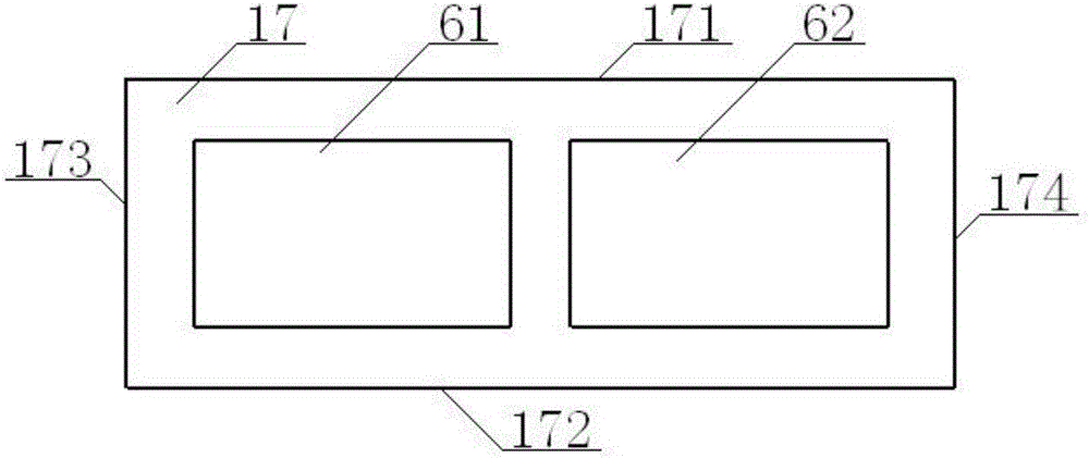
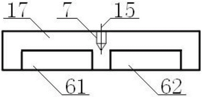
[0042] see Figure 1 to Figure 5 , a wheel side reduction axle with oil return groove and oil retaining groove, including axle housing 1, central reducer 2, half shaft 3, said central reducer 2, half shaft 3 are arranged in axle housing 1, central reducer 2 includes the driving gear and the driven gear 21, the left end of the central reducer 2 is connected with the left wheel reducer 4 through the half shaft 3, and the right end of the central reducer 2 is connected with the right wheel reducer 5 through the half shaft 3, so The axle housing 1 includes an axle pack 11 and bridge tubes 12 provided at both ends of the axle pack 11. The upper cover plate 17 of the axle pack 11 is provided with an oil return tank 6, and the rear end of the axle pack 11 is provided with a bridge connected thereto. Housing rear cover 9, the axle housing rear cover 9 is provided with an oil retaining groove 10, and the oil return groove 6 and the oil retaining groove 10 are integrally casted with the...
Embodiment 2
[0044] Basic content is the same as embodiment 1, the difference is:
[0045] see Figure 1 to Figure 5 , the oil return tank 6 includes a No. 1 oil return tank 61 and a No. 2 oil return tank 62 , the No. 1 oil return tank 61 is located on the left side of the inner surface of the upper cover plate 17 , and the No. 1 oil return tank 61 is located on the upper left of the driven gear 21 The No. 2 oil return tank 62 is located at the right part of the inner surface of the upper cover plate 17, and the No. 2 oil return tank 62 is located at the upper right of the driven gear 21; the middle part of the upper cover plate 17 is provided with a positioning pin hole 7, The positioning pin hole 7 is located at the position between the No. 1 oil return groove 61 and the No. 2 oil return groove 62, and the center line of the positioning pin hole 7 is coaxial with the No. 1 center line 15 of the bridge pack 11; No. oil return tank 62 is cuboid structure, and the length of No. 1 oil retur...
Embodiment 3
[0047] Basic content is the same as embodiment 1, the difference is:
[0048] see Figure 1 to Figure 5 , the oil retaining groove 10 is a cylindrical structure, one side of the oil retaining groove 10 is connected with the upper left part of the rear cover 9 of the axle housing, the oil retaining groove 10 is perpendicular to the No. 2 centerline 16 of the bridge tube 12, and the oil retaining groove 10 includes Oil tank body 101, oil retaining tank through hole 102, the oil retaining tank through hole 102 is located in the middle of the oil retaining tank body 101, the centers of the oil retaining tank through hole 102 and the oil retaining tank body 101 are the center of circle 103, the oil retaining tank through hole 102 and the axle housing The back cover 9 communicates; the outer diameter of the oil retaining groove body 101 is 80 millimeters, the height of the oil retaining groove body 101 is 150 millimeters, the diameter of the oil retaining groove through hole 102 is ...
PUM
 Abstract
Description
Claims
Application Information
 - R&D
- Intellectual Property
- Life Sciences
- Materials
- Tech Scout
- Unparalleled Data Quality
- Higher Quality Content
- 60% Fewer Hallucinations
Browse by: Latest US Patents, China's latest patents, Technical Efficacy Thesaurus, Application Domain, Technology Topic, Popular Technical Reports.
© 2025 PatSnap. All rights reserved.Legal|Privacy policy|Modern Slavery Act Transparency Statement|Sitemap|About US| Contact US: help@patsnap.com


