Conveyor system for conveying objects and control process for such a system

a conveyor system and conveying technology, applied in the field of conveying systems, can solve the problems of high cost, high cost, and high difficulty of conventional individual control, and achieve the effect of preventing damage to objects or people, and increasing the flexibility of the conveying system

Inactive Publication Date: 2017-07-18
EISENMANN SE
View PDF9 Cites 1 Cited by
  • Summary
  • Abstract
  • Description
  • Claims
  • Application Information

AI Technical Summary

Benefits of technology

[0010]The assignment of a superordinate status to a first conveyor unit and a subordinate status to one (or more) second conveyor unit(s) enables the routes of the conveyor units to be matched very precisely to one another because the second conveyor unit with the subordinate status is orientated directly on the route of the conveyor unit with the superordinate status. With this, the second conveyor unit determines a shift in the mutual relative position of the first and the second conveyor unit with the aid of a sensor and matches their driving parameters, such as velocity and steering angle, accordingly. Undesired deviations between the routes can therefore be considerably reduced. It is thus possible to prevent conveyor units which are driven in groups from colliding and to prevent objects which are conveyed together from slipping.
[0011]In some instances, it is also possible to reduce the complexity involved in controlling the conveyor units because only the first conveyor unit with the superordinate status has to find its way. On the other hand, it is possible to dispense with separate localisation and navigation for the second conveyor unit with the subordinate status.
[0014]The central control of the conveyor system may combine conveyor units to form conveyor devices according to requirements, with it being possible to source the necessary conveyor units from conveniently situated stocks of the conveyor system. A failure of a conveyor unit therefore involves a relatively short down time of the conveyor system, which increases the availability of the conveyor system.
[0021]It is particularly advantageous if, when driving in a direction which is perpendicular to the longitudinal axis of the conveyor device, axes of all floor rollers of the first conveyor unit are coaxial, and axes of all floor rollers of the second conveyor unit are coaxial. The fact that the load carrier is used as a connecting element enables a particularly flexible driving mode of the conveyor device which cannot be executed by the individual components. It is thereby possible to realise a change in direction of the conveyor device through 90° without cornering. In particular, by means of this driving mode, it is rapidly possible to achieve precise positioning of the conveyor unit within a relatively small space, for example when loading a lorry.
[0024]In an embodiment, provision is made to enable the subordinate and the superordinate status of the conveyor units to be switched at any time. For example, if the sensor of the conveyor unit with the subordinate status fails, with the result that a shift in the mutual relative position of the first and the second conveyor unit cannot be detected any more, this conveyor unit can continue its journey in the superordinate position. To this end, if the sensor is only arranged on one longitudinal side, the conveyor units are re-orientated so that the required orientation is re-established. It is alternatively possible to use conveyor units which do not have any asymmetry in terms of their structural design. The flexibility of the conveyor system is thereby increased considerably.
[0025]Provision can furthermore be made to enable the conveyor units to find their route by means of cameras or other sensors. To prevent damage to objects or people, each conveyor unit can comprise safety devices which detect items or persons located on the route and communicate this to the central control or the control device of the conveyor unit so as to implement a change in the driving parameters. The sensors here can be arranged on one or both end faces of the conveyor unit.

Problems solved by technology

If the spacing between the conveyor units of a group is too small, there is for example the risk of conveyor units colliding in the event of the conveyor units deviating slightly from their intended route.
Difficulties also arise when an object is to be conveyed jointly by two mechanically separate conveyor units.
In such cases, the conventional individual control is rapidly limited because the deviations from the intended routes are often too great.

Method used


Image

  • Conveyor system for conveying objects and control process for such a system
  • Conveyor system for conveying objects and control process for such a system
  • Conveyor system for conveying objects and control process for such a system

Examples


Embodiment Construction

[0038]While this invention is susceptible of embodiment in many different forms, there is shown in the drawings and will herein be described in detail one or more embodiments with the understanding that the present disclosure is to be considered as an exemplification of the principles of the invention and is not intended to limit the invention to the embodiments illustrated.

[0039]Basic Construction of the Conveyor System

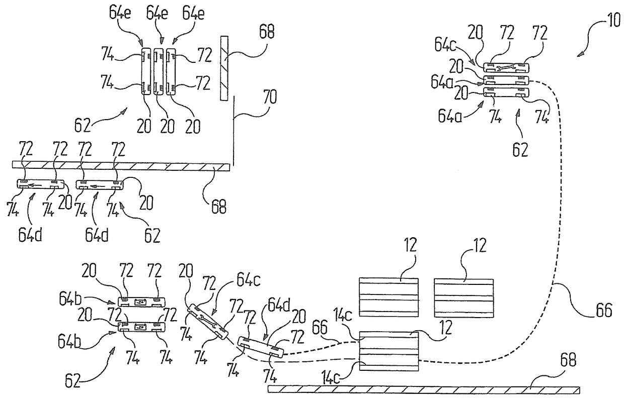
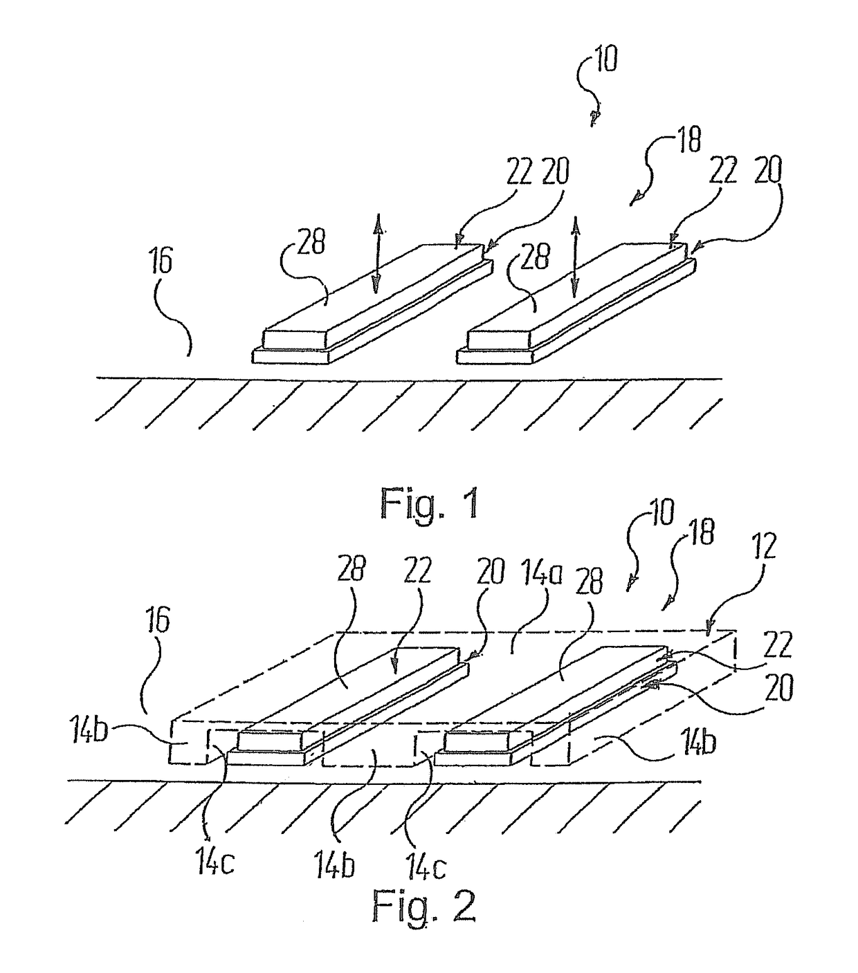
[0040]In the Figures, 10 denotes a conveyor system as a whole, by means of which objects—laden or unladen load carriers 12 in this case—can be conveyed. FIG. 2 shows a pallet, such as is known per se, as an example of a load carrier 12.

[0041]A load carrier 12 has a supporting surface 14a on which material to be conveyed (not shown specifically) can be deposited and fastened. The supporting surface 14a rests on a floor 16 by way of bearing elements 14b. A respective opening 14c remains between two adjacent bearing elements 14b and is open downwards towards the floor 1...


PUM


Abstract

A control process for a conveyor system for conveying pallets or other objects comprises at least two mutually separate free-moving, i.e. not rail-mounted, conveyor units. Of the at least two conveyor units, a first conveyor unit is assigned a superordinate status and a second conveyor unit is assigned a subordinate status. The second conveyor unit therefore follows the first conveyor unit. To this end, the second conveyor unit detects a shift in the mutual relative position of the two conveyor units with the aid of a sensor and modifies its driving parameters depending on the shift in position detected by the sensor.

Description

CROSS-REFERENCE TO RELATED APPLICATIONS[0001]The present application claims benefit of German patent application no. 10 2014 016 900.6 filed Nov. 17, 2014—the full disclosure of this application is incorporated herein by reference.BACKGROUND OF THE INVENTION[0002]Field of the Invention[0003]The invention relates to a conveyor system for conveying objects such as pallets or other load carriers, which comprises at least two mutually separate conveyor units, and a control process for such a conveyor system.[0004]Description of the Prior Art[0005]DE 10 2008 014 877 A1 discloses a conveyor system in which in each case two conveyor units in the style of a transport trolley form a conveyor device, with two transport trolleys being designed to convey load carriers in the form of pallets. To this end, the two transport trolleys can move under a pallet as a transport-trolley pair, then lift it and convey it to another location. In particular, the conveyor system enables automatic loading of p...

Claims


Application Information

Patent Timeline
Patent Type & Authority Patents(United States)
IPC IPC(8): G06F7/00G05B19/418B62B5/00B62B3/06
CPCG05B19/41835B62B5/0093B62B3/0612B62B5/0033B62B5/0083G05B2219/25385G05D2201/0216G05D1/0293
Inventor SCHULZE, HERBERTVETTER, SVENJA
Owner EISENMANN SE
Why Eureka
Try Eureka