Refrigeration device
a technology of refrigerating device and high-pressure air conditioner, which is applied in the direction of refrigerating machines, lighting and heating apparatus, compression machines with reversible cycles, etc., can solve the problems of reducing the durability of the members constituting the high-pressure part of the air conditioner, and achieve the effect of significantly reducing the heat loss of the heating operation
- Summary
- Abstract
- Description
- Claims
- Application Information
AI Technical Summary
Benefits of technology
Problems solved by technology
Method used
Image

Examples
first embodiment
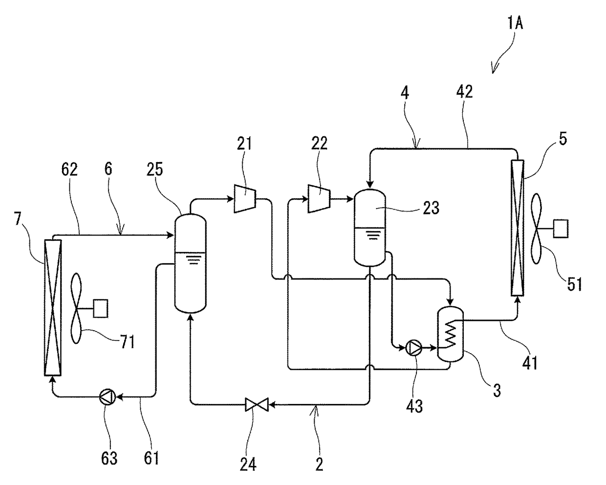
[0041]FIG. 1 shows an air conditioner 1A according to the first embodiment of the present invention. This air conditioner 1A includes: a refrigerant circuit 2 that allows a refrigerant to circulate; a heat release circuit 4 that allows a heat medium to circulate to cool the refrigerant; and a heat absorption circuit 6 that allows a heat medium to circulate to heat the refrigerant.
[0042]In the present embodiment, the heat release circuit 4 and the heat absorption circuit 6 are each a circuit that merges into the refrigerant circuit 2 to bring the heat medium into direct contact with the refrigerant, and the refrigerant circuit 2, the heat release circuit 4, and the heat absorption circuit 6 are filled with the same refrigerant. That is, a portion of the refrigerant is used as the heat medium. This refrigerant is a refrigerant whose saturated vapor pressure is a negative pressure at ordinary temperature, for example, a refrigerant whose main component is water, alcohol or ether, and t...
second embodiment
[0077]FIG. 5 shows an air conditioner 1B according to the second embodiment of the present invention. In the second to fourth embodiments, the same components as those in the first embodiment are denoted by the same reference numerals, and the description thereof is partially omitted.
[0078]In the present embodiment, the vapor cooler 3 is not disposed on the heat release circuit 4 but on the heat absorption circuit 6. That is, the vapor cooler 3 of the present embodiment is a heat exchanger that exchanges heat between the refrigerant vapor compressed by the first compressor 21 and the refrigerant liquid flowing in the heat absorption circuit 6. More specifically, the vapor cooler 3 is disposed downstream from the pump 63 in the heat absorption side feed path 61.
[0079]In the present embodiment, since the refrigerant vapor can be cooled using the refrigerant liquid having a lower temperature than that in the first embodiment, the temperature of the refrigerant to be drawn into the seco...
third embodiment
[0088]FIG. 8 shows an air conditioner 1C according to the third embodiment of the present invention. This air conditioner 1C includes the refrigerant circuit 2, the heat release circuit 4, and the heat absorption circuit 6. The structures and functions of these circuits are as described in the first embodiment. A vapor cooler 8 is disposed on the refrigerant circuit 4.
[0089]The vapor cooler 8 is a heat exchanger that exchanges heat between the refrigerant vapor compressed by the first compressor 21 and air, and cools the refrigerant vapor discharged from the first compressor 21 before the refrigerant vapor is drawn into the second compressor 22. In the present embodiment, the vapor cooler 8 is disposed indoors. As the vapor cooler 8, for example, a fin-and-tube heat exchanger can be used.
[0090]In the present embodiment, the above-mentioned vapor cooler 8 is disposed in such a manner that a wind generated by an air blower 51 (an indoor fan 51) passes through the first heat exchanger ...
PUM
 Abstract
Description
Claims
Application Information
 - R&D
- Intellectual Property
- Life Sciences
- Materials
- Tech Scout
- Unparalleled Data Quality
- Higher Quality Content
- 60% Fewer Hallucinations
Browse by: Latest US Patents, China's latest patents, Technical Efficacy Thesaurus, Application Domain, Technology Topic, Popular Technical Reports.
© 2025 PatSnap. All rights reserved.Legal|Privacy policy|Modern Slavery Act Transparency Statement|Sitemap|About US| Contact US: help@patsnap.com