
Multi-needle sewing machine

a needle thread and needle thread technology, applied in the field of needle thread sewing machines, can solve the problems of difficulty in setting needle threads by users

Active Publication Date: 2017-08-22
BROTHER KOGYO KK
View PDF14 Cites 4 Cited by
  • Summary
  • Abstract
  • Description
  • Claims
  • Application Information

AI Technical Summary

Benefits of technology

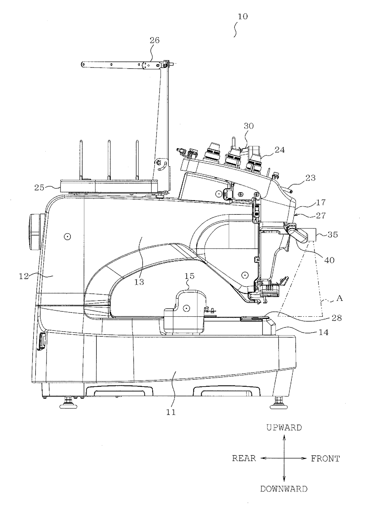
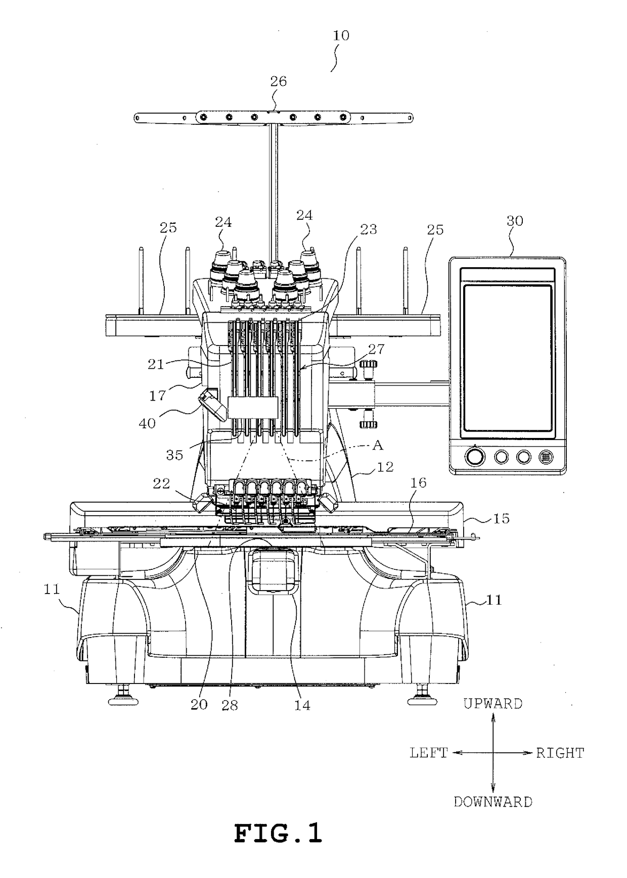
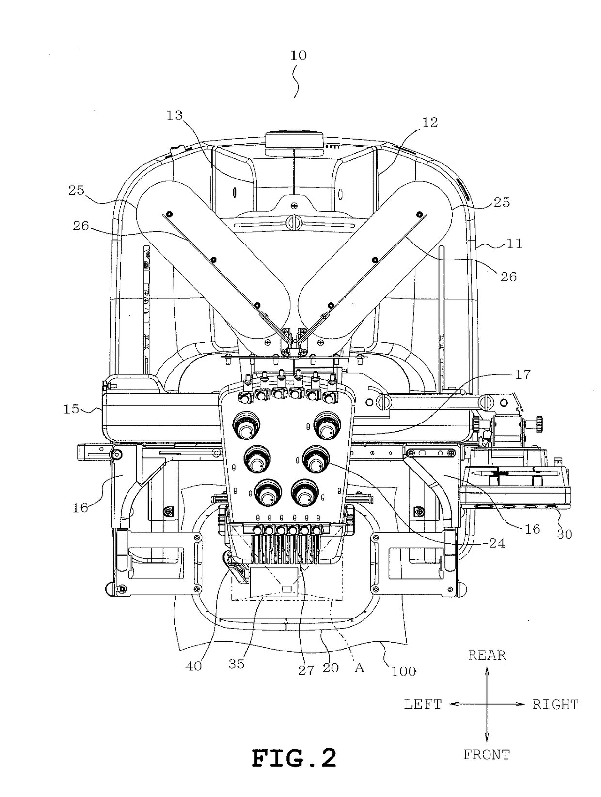
[0008]Therefore, an object of the disclosure is to provide a multi-needle sewing machine which is provided with a projector projecting an image onto the workpiece cloth and can prevent the projector from getting in the way of user's work to set needle threads along the needle thread path.

Problems solved by technology

Accordingly, when disposed at the front side of the needle bar case, the projector gets in the way of user's work to set needle threads along the needle thread path, with the result that the user has difficulty in setting the needle threads.

Method used


Image

  • Multi-needle sewing machine
  • Multi-needle sewing machine
  • Multi-needle sewing machine

Examples


second embodiment

[0069]The support device 60 includes a first support member 61, a second support member 62 and a screw member 63 as shown in FIGS. 13A and 13B. The screw member 63 is constructed in the same manner as the screw member 55 in the The first support member 61 has a front 611 and a right side 612 and is formed into an L-shape as viewed in a plan view, as shown in FIGS. 13A and 13B. The second support member 62 has a front 621 and a left side 622 and is formed into an L-shape. The first and second support members 61 and 62 are combined together into a U-shape having an open needle bar case 17 side or rear side and two substantially right-angled corners. The projector 35 is fixed to the front 611 of the first support member 61.

[0070]The front 611 of the first support member 61 has a distal end, namely, a left end formed with a groove 613 and a female screw hole (not shown) located inside the groove 613. The front 621 of the second support member 62 is constructed to fit into the groove 61...

third embodiment

[0077]Further, a sensor may be separately provided for detecting attachment or detachment of the support device 60 in the


PUM


Abstract

A multi-needle sewing machine includes a plurality of needle bars, a needle bar case having a thread supply path along which threads are supplied to needles attached to lower ends of the needle bars respectively, the needle bar case supporting the needle bars, an arm on which the needle bar case is mounted, an embroidery frame located below the needle bar case and configured to hold a workpiece cloth, a projector configured to project an image onto the workpiece cloth from above the embroidery frame, and a support member supporting the projector and configured to be capable of switching the projector between a first position where the image is projectable onto the workpiece cloth and a second position differing from the first position.

Description

CROSS-REFERENCE TO RELATED APPLICATIONS[0001]This application is based upon and claims the benefit of priority from the prior Japanese Patent Application No. 2013-272141 filed on Dec. 27, 2013, the entire contents of which are incorporated herein by reference.BACKGROUND[0002]1. Technical Field[0003]The present disclosure relates to a multi-needle sewing machine including a plurality of needle bars and a needle bar case supporting the needle bars.[0004]2. Related Art[0005]There has conventionally been known a sewing machine provided with a projector which projects an image onto an object. For example, a household sewing machine includes a single needle bar and a projector mounted on a head of the sewing machine. In use of the sewing machine, the projector projects an image of embroidery pattern assuming a finished piece onto a workpiece cloth. A user can exactly confirm a position of the embroidery pattern before sewing while viewing the image of embroidery pattern projected on the w...

Claims


Application Information

Patent Timeline
Patent Type & Authority Patents(United States)
IPC IPC(8): D05B1/08D05B51/00D05B79/00D05C13/00
CPCD05B79/00D05B51/00D05C13/00
Inventor SHIMIZU, AKIENISHIMURA, YOSHIONOMURA, YUTAKAIHIRA, YUKIOTA, MANAMIOKA, HIDENORIICHIYANAGI, SATORU
Owner BROTHER KOGYO KK
Learn More