
Data cable for high-speed data transmissions

a data cable and high-speed technology, applied in the direction of cables/conductor manufacture, cable/conductor manufacturing, electrical equipment, etc., can solve the problems of low processing speed high attenuation peak at high frequencies, etc., and achieve good transmission properties

Active Publication Date: 2017-08-22
BIZLINK IND GERMANY GMBH
View PDF10 Cites 3 Cited by
  • Summary
  • Abstract
  • Description
  • Claims
  • Application Information

AI Technical Summary

Benefits of technology

[0012]It is accordingly an object of the invention to provide a data cable for high-speed data transmissions, which overcomes the hereinafore-mentioned disadvantages of the heretofore-known cables of this general type and which has good transmission properties even at high transmission rates and high transmission frequencies.
[0015]In principle, there would be the possibility to shift the attenuation frequency toward higher frequencies by geometrical measures such as, for example, a shorter length of lay. In the ParaLink cables described in the introduction, this is obtained by a very steep pitch of the winding. The length of lay in this case is, in particular, approximately 3 mm, so that the peak-type insertion loss and hence also the return loss lies above 25 GHz. According to the currently applicable standards, such a peak in such lines must not occur within the frequency range up to 25 GHz. However, due to the more intense wrapping, the short length of lay results in a low processing speed in the course of the wrapping of the pair of wires, leading to higher costs.
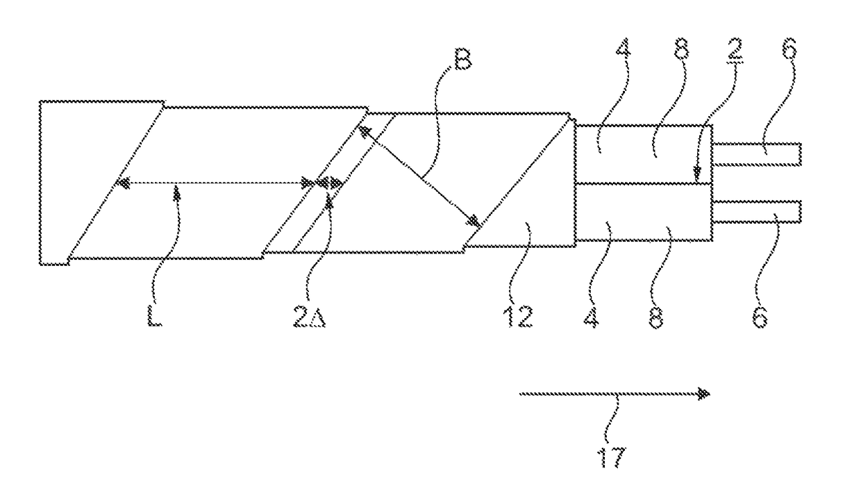
[0016]Accordingly, in conventional data cables with the intermediate film, a comparatively large attenuation (attenuation peak) occurs by reason of the addition of all of the individual reflections at a fixed, narrow frequency. As a result, a high attenuation of the signal occurs, so that the requirements of the so-called insertion loss for high transmission frequencies are only inadequately satisfied. In contrast, by reason of the varying length of lay, an attenuation peak is no longer present at a fixed frequency, so that the requirements of the insertion loss are even satisfied at high frequencies. At the same time, as a result there is the possibility to lengthen the length of lay and hence to increase the processing speed and consequently lower the costs.
[0019]The mean length of lay of the intermediate film in this case preferentially lies within the range of a few millimeters, in particular within the range from 5 mm to 15 mm. In particular, the mean length of lay in this case lies approximately between 6 mm and 8 mm. With this length of lay, a fast and reliable production of the wrapping of the intermediate film, in terms of process engineering, is made possible. A high processing speed is achieved. At the same time, the properties desired with the intermediate film can be obtained in this way, namely a defined, fixed wrapping of the pair of wires, in order to place the shielding foil attached over it in a defined uniform geometry around the pair of wires, so that no symmetrical points of interference of the shielding foil have been formed.

Problems solved by technology

This results, therefore, in a high attenuation peak at high frequencies in the case of the so-called insertion loss.
By virtue of the periodic structure, in addition this also results in a high attenuation peak at high frequencies in the case of the so-called return loss.
However, due to the more intense wrapping, the short length of lay results in a low processing speed in the course of the wrapping of the pair of wires, leading to higher costs.

Method used


Image

  • Data cable for high-speed data transmissions
  • Data cable for high-speed data transmissions
  • Data cable for high-speed data transmissions

Examples


Embodiment Construction

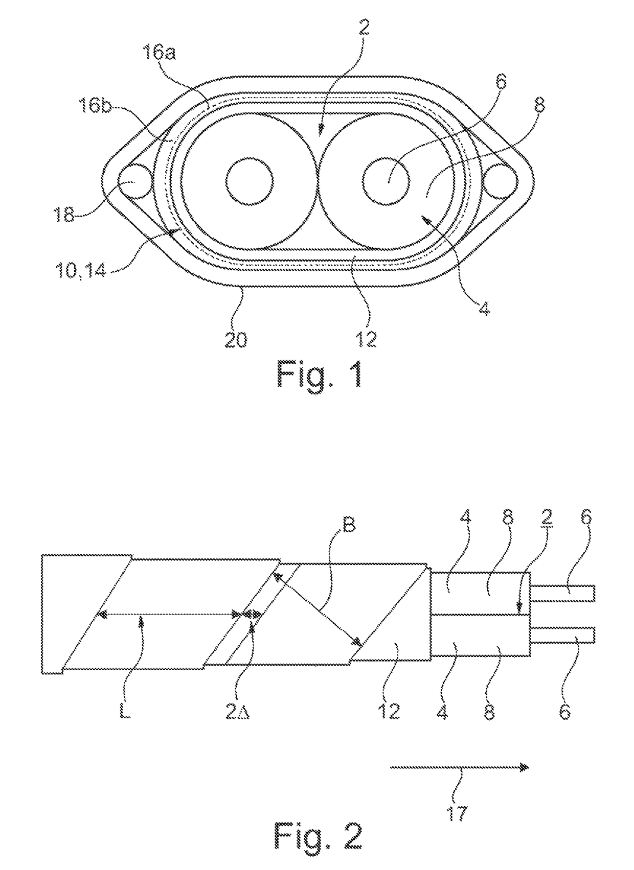
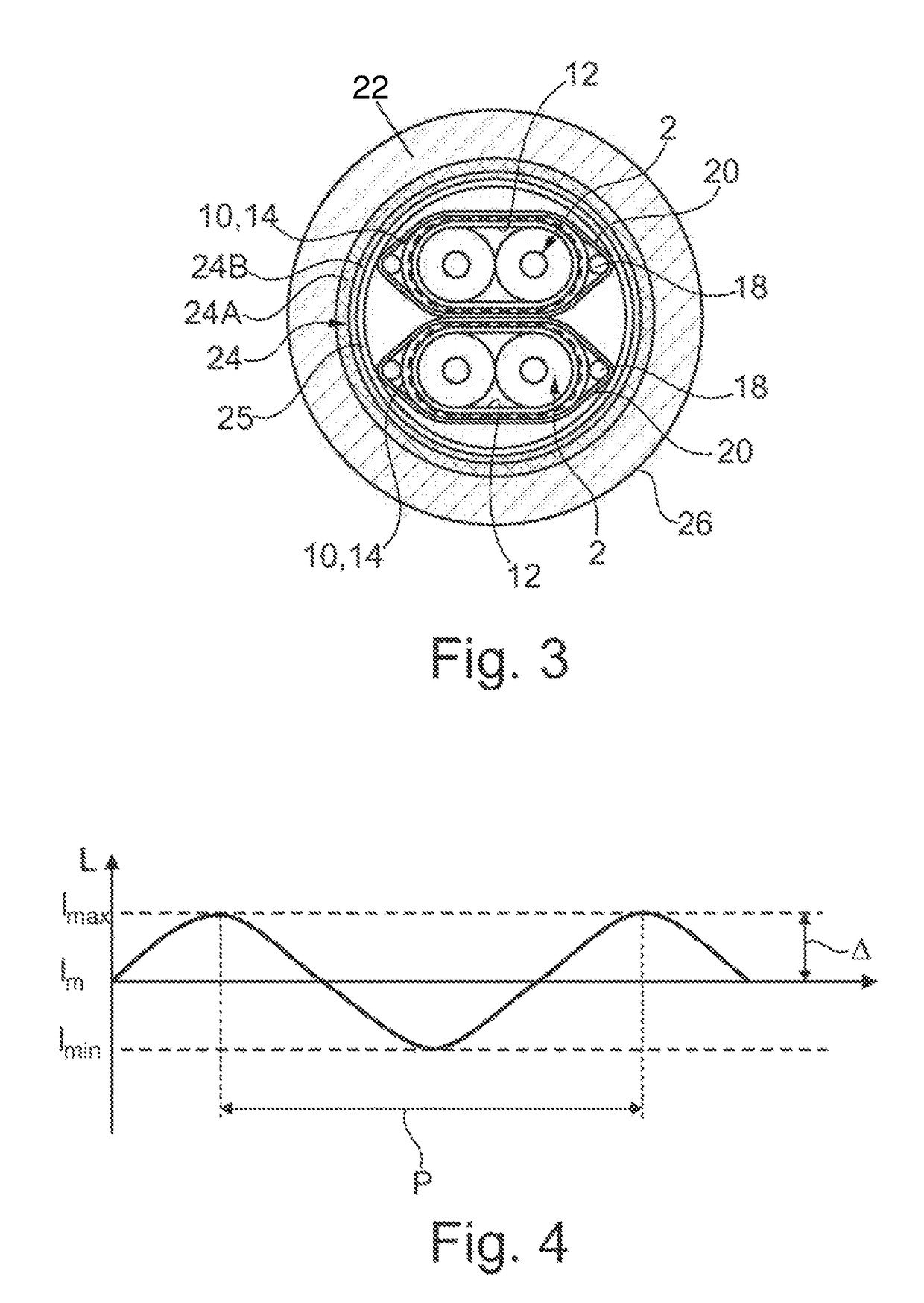
[0040]Referring now to the figures of the drawings in detail and first, particularly, to FIGS. 1-3 thereof, there is seen at least one wire pair 2, formed of two wires 4, in which each wire 4 in turn exhibits a central conductor 6 which is surrounded by a wire insulation 8. The wire pair 2 is surrounded in each instance by a pair shielding 10 which surrounds the wire pair 2, with the insertion or interposition of an intermediate film 12.

[0041]In the embodiment variant according to FIG. 1, the pair shielding 10 has been formed by a single multilayered shielding foil 14 which is formed of a backing layer 16a taking the form of a PET backing film and also an aluminum coating, attached thereto, by way of a conductive layer 16b. The conductive layer 16b is oriented outward. In the case of the shielding foil 14, a longitudinally folded shielding foil 14 is used having longitudinal edges which therefore run parallel to the wires 4 in a longitudinal direction 17. The wires 4 run in the long...


PUM

PropertyMeasurementUnit
mean lengthaaaaaaaaaa
lengthaaaaaaaaaa

Abstract

A data cable for high-speed data transmissions includes at least one wire pair formed of wires extending in a longitudinal direction and being surrounded by a shielding foil to form a pair shielding. A dielectric intermediate film or foil having a varying lay length is spun around the wire pair between the shielding foil and the wire pair, in order to effectively avoid a damping peak at high transmission frequencies.

Description

CROSS-REFERENCE TO RELATED APPLICATION[0001]This is a continuation application, under 35 U.S.C. §120, of copending International Application PCT / EP2015 / 065034, filed Jul. 1, 2015, which designated the United States; this application also claims the priority, under 35 U.S.C. §119, of German Patent Application DE 10 2014 214 726.3, filed Jul. 25, 2014; the prior applications are herewith incorporated by reference in their entirety.BACKGROUND OF THE INVENTIONField of the Invention[0002]The invention relates to a data cable for high-speed data transmissions, including at least one wire pair formed of two wires extending in a longitudinal direction and being surrounded pairwise by a shielding foil in order to form a pair shielding, and a non-conductive intermediate film being spun around the wire pair as an additional film between the shielding foil and the wire pair. Such a data cable is being offered for sale by Leoni Cables and Systems of San Jose, Calif. under the brand name “23 Para...

Claims


Application Information

Patent Timeline
Patent Type & Authority Patents(United States)
IPC IPC(8): H01B11/00H01B13/18
CPCH01B11/002H01B11/203
Inventor JANSSEN, BERNDDETTMER, MELANIE
Owner BIZLINK IND GERMANY GMBH
Learn More