Height adjustable concrete form assembly

a technology of height adjustment and concrete, applied in the field of forms, can solve problems such as wear and tear, and achieve the effects of improving height adjustment, enhancing height adjustment function, and economical concrete structure production

Active Publication Date: 2017-09-05
METAL FORMS
View PDF16 Cites 5 Cited by
  • Summary
  • Abstract
  • Description
  • Claims
  • Application Information

AI Technical Summary

Benefits of technology

[0005]Advantages are achieved by the present concrete form assembly which includes an improved height adjustment and an economical concrete structure production. The present height adjustable concrete form assembly includes a top spacer assembly, a bottom spacer assembly, a front barrier assembly, and a rear barrier assembly, having at least one height adjustment assembly. As discussed in greater detail below, the present concrete form assembly provides an enhanced height adjustment function for concrete structure construction using the height adjustment assembly.
[0006]In operation, the use of the height adjustment assembly eliminates a need for attaching an additional riser assembly to the concrete form to achieve various required heights. Conventionally, a separate 4-inch riser assembly is attached on top of a 32-inch barrier assembly on each front and rear barrier wall to create a 36-inch tall barrier assembly. In the present invention, the height adjustment assembly can be used to alter an overall height of the form without adding or removing the riser assembly.
[0007]For example, at least one jackscrew mechanism of the height adjustment assembly is manually or mechanically turned clockwise or counterclockwise to decrease or increase the height of the form for leveling purposes. There is no need to attach or remove the riser assembly to and from the form, or purchase extra riser assemblies. Thus, the present adjustable form assembly provides an efficient means of height adjustment without causing additional delays and operating costs.
[0009]For example, during the frequent use of leveling feature of the form, there may be increasing torque being applied on the jackscrew mechanism when two opposite-end jackscrews are not raised in unison. Instead of allowing excessive wear and tear on the jackscrew mechanism, the roll pin selectively shears when disproportionate travel or torque is applied on one of the jackscrews during operation. This protective mechanism protects the height adjustment assembly, and allows an effortless replacement of the jackscrew mechanism without having to replace the entire height adjustment assembly.
[0012]In yet another embodiment, a barrier assembly used in a form assembly is provided for forming a concrete structure during setting of the concrete. The barrier assembly includes an upper barrier having at least one upper side plate attached to an outer surface of the upper barrier. A lower barrier has at least one lower side plate attached to an outer surface of the lower barrier. A height adjustment assembly is connected at one end to the upper barrier, and at an opposite end to the lower barrier such that the height adjustment assembly increases or decreases an overall height or slope of the upper barrier relative to the lower barrier. A plurality of bores are provided in corresponding upper and lower side plates to provide a serial attachment of two adjacent form assemblies using fasteners through the plurality of bores.

Problems solved by technology

Over an operational life of the form, many adjustments are typically performed on the height adjustment assembly, thereby exhibiting signs of wear and tear.

Method used


Image

  • Height adjustable concrete form assembly
  • Height adjustable concrete form assembly
  • Height adjustable concrete form assembly

Examples


Embodiment Construction

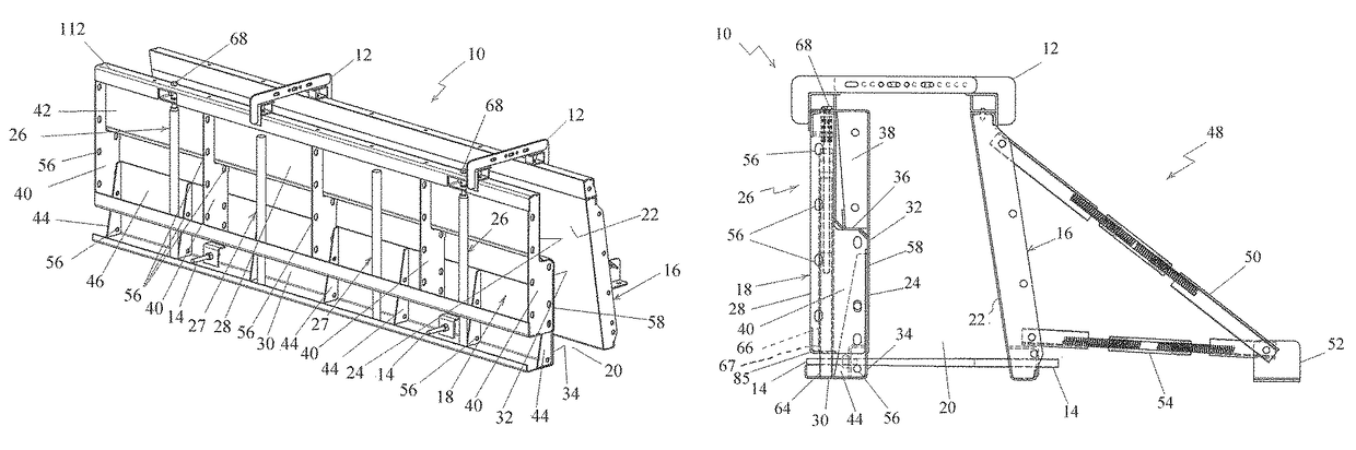
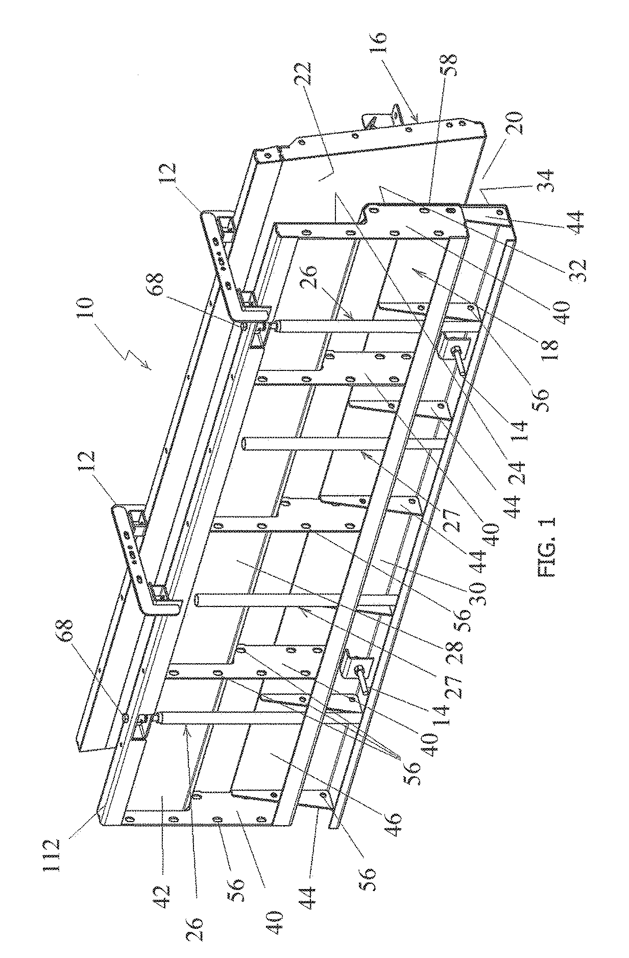
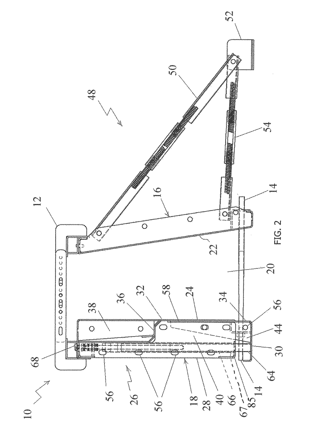
[0023]Referring now to FIGS. 1-3, the present concrete form assembly is generally designated 10, and is designed to provide an efficient way to adjust an overall height of the form assembly, and also to perform enhanced concrete constructions without incurring substantial operational delays and costs. Included in the present form assembly 10 are a top spacer assembly 12, a bottom spacer assembly 14, a first or front barrier assembly, generally designated 16, and a second or rear barrier assembly, generally designated 18. When pouring concrete into a channel 20 defined by inner surfaces 22, 24 of the first and second barrier assemblies 16, 18, the top and bottom spacer assemblies 12, 14 hold the form assembly 10 in its original shape such that the poured concrete can be cured and hardened without disfigurement or interruption.

[0024]Each second or rear barrier assembly 18 includes at least one height adjustment assembly, generally designated 26, an upper barrier 28, and a lower barrie...


PUM

PropertyMeasurementUnit
length L1aaaaaaaaaa
length L2aaaaaaaaaa
heightaaaaaaaaaa

Abstract

A form assembly is provided for forming a concrete structure during setting of the concrete. Included in the form assembly are a first barrier assembly having a first inner surface and a first outer surface; a second barrier assembly having a second inner surface, a second outer surface, an upper barrier, and a lower barrier. A channel is defined by the first and second inner surfaces of the first and second barrier assemblies for pouring the concrete into the channel. The second barrier assembly includes at least one height adjustment assembly being connected at one end to the upper barrier, and at an opposite end to the lower barrier such that the upper barrier vertically reciprocates along a vertical guide of the upper barrier relative to the lower barrier for adjusting an overall height of the form assembly using the at least one height adjustment assembly.

Description

FIELD OF THE INVENTION[0001]The present invention generally relates to forms used for pouring concrete structure, and more specifically, to a height adjustable form assembly that may be used for pouring concrete structures of varying heights. Further, the present invention relates to a device for connecting adjustable forms used for pouring concrete structures.BACKGROUND OF THE INVENTION[0002]Concrete forms are often used for the purpose of pouring concrete structures, such as curbs, walls, sidewalks, or other structures of varying shapes. Typically, flexible or rigid sheet metal forms or wooden forms are used, and more recently plastic forms have been employed. In concrete construction, it is customary to erect a concrete barrier or bulkhead across the form to hold the poured concrete while the concrete becomes set or hardened, and produces an individual finished wall or slab section. When the hardening (or setting) of the concrete is completed, the barrier or bulkhead is dismantle...

Claims


Application Information

Patent Timeline
Patent Type & Authority Patents(United States)
IPC IPC(8): B28B7/02E04G17/14E01C19/48E04G17/12E04G13/00
CPCB28B7/02E01C19/4886E04G13/00E04G17/12E04G17/14E01C19/506
Inventor DAUL, JUSTIN
Owner METAL FORMS
Why Eureka
Try Eureka