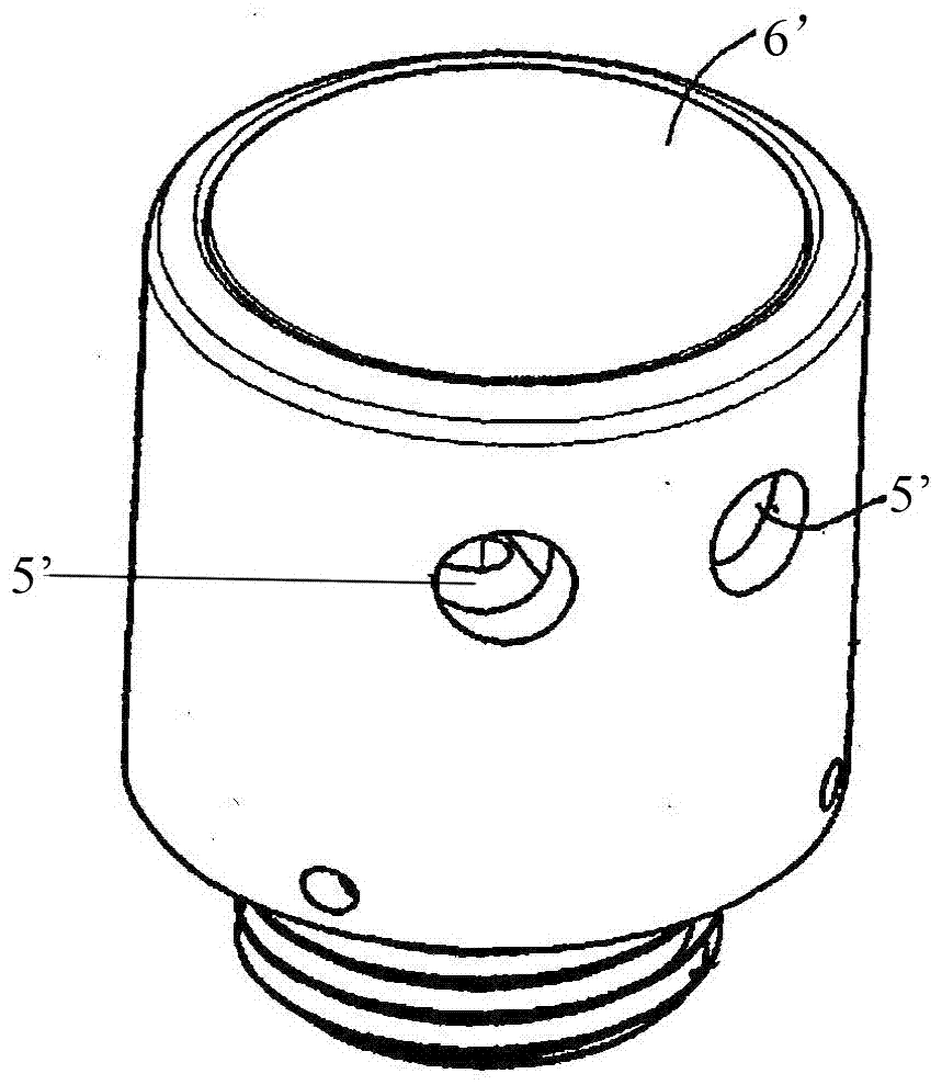
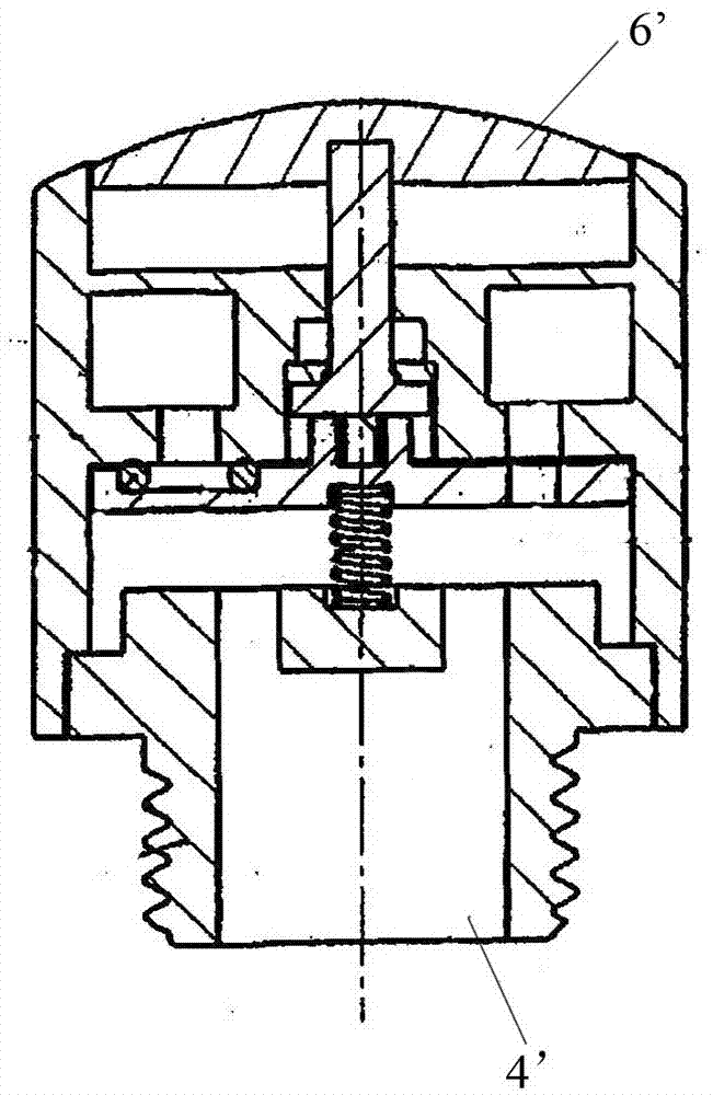
[0002] Applying the principle of automatic ballpoint pen switching to the bathroom field first appeared in the
patent literature of CN101793331A, such as Picture 1-1 , Figure 1-2 As shown, it discloses the working method of switching the waterway through the button, but this kind of waterway switching is limited to the water inlet 4' and at least two water outlets 5' perpendicular to each other, that is, if the water inlet 4' is located at the bottom of the valve body, Then the two water outlets 5' are located in the
radial position of the valve body. This waterway switching method has a narrow application area and can only be applied to
shower or top spray products; at the same time, when the switching valve body is placed horizontally, push the button After 6' is pressed, because the button 6' has no self-weight limit, it is easy to form a
virtual position, that is, the position of the button 6' after pressing may be consistent with the position of the button 6' in the pop-up state, and the
stroke of the button 6' cannot be recognized at this time Position to determine which water inlet 4' is connected to which outlet 5'
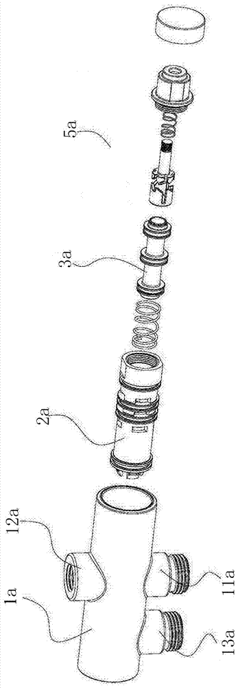
[0003] In view of this, the industry has disclosed another push-button water distribution device, refer to the announcement number CN205036896U, such as Figure 2-1 , Figure 2-2 As shown, a radial water inlet 11a, a radially upper water outlet 12a, and a radially lower water outlet 13a are provided on the side wall of the
water diversion body 1a, and the switching valve 2a is placed in the inner cavity of the
water diversion body 1a. The pressing mechanism 5a of the principle drives the valve core 3a to reciprocate along the axis of the switch valve 2a, so that one of the water inlet 11a and the upper water outlet chamber 6a or the lower water outlet chamber 7a can be connected to each other, thus forming different switching waterways. Realized that the water inlet 11a and the upper and lower water outlets 12a, 13a are all located in the
radial position of the switch valve 2a, which can facilitate the arrangement of the lifting rod and the hand-held
shower on the water distribution device 1a, but this kind of scheme is in order to realize The spool 3a and the inner cavity of the switching valve 2a form two closed waterways, so three sealing rings 32a need to be provided on the outer ring wall of the spool 3a. When the spool a3 moves back and forth, its sealing ring 32a and the switching valve The inner
cavity wall of 2a produces friction, which causes the pressing mechanism 5a to produce greater
frictional resistance when pressing; secondly, the sealing ring 32a will
wear out when it is repeatedly rubbed, which will easily cause
water leakage in the switching valve 2a and shorten the service life. At the same time, the upper water outlet chamber 6a and the lower water outlet chamber 7a of this kind of water distribution device are set at the radial position of the switching valve 2a, so that when the valve core 3a switches the
water channel, the upper water outlet chamber 6a or the lower water outlet chamber 7a The
water channel switching can only be realized after the water in the chamber is squeezed out, so that the pressing mechanism 5a will produce a certain
delay effect when pressing and switching
[0004] At the same time, the above two push-button switching valves cannot realize the function of flow switching at the same time. If flow control is required, an additional flow control valve must be added to adjust the flow. Sometimes due to the limitation of the installation space, it cannot be installed, or Considering the overall simple visual effect, both the flow regulating valve and the switching valve are installed on a water outlet device, and the overall
layout is complicated

