Method and system for tunnel ventilation in normal conditions and in conditions of fire

a tunnel ventilation and normal condition technology, applied in mining structures, fire rescue, earthwork drilling and mining, etc., can solve the problems of not providing a stationary state, cannot prevent the influx of fresh air to the place, and none of the existing patented tunnel ventilation systems can meet the requirements for passenger and tunnel protection in tunnels of greater length, so as to reduce the oxygen content and increase/decrease the value of measured parameters

Active Publication Date: 2017-09-05
PAVETIC JOSIP +2
View PDF40 Cites 9 Cited by
  • Summary
  • Abstract
  • Description
  • Claims
  • Application Information

AI Technical Summary

Benefits of technology

[0042]The operation capacity and direction of the fans (3, 3a) is controlled by measuring the air velocity v and the O2, CO concentrations and air visibility in the tunnel in dependence on the designed air velocity v2 and at least one air screen (6a) is switched on / off, whereby the influx of the designed air quantity from the environment into the tunnel is regulated and the designed air motion is achieved in normal conditions, in the conditions corresponding to the values of the measured parameters outside the permissible limits and in fire conditions prevailing in the fire zone. In the fire zone, after attaining the positions of the adjacent flaps (5) in a way that they close the middle duct or direct the air flow in all three ventilation ducts and by regulating the operation capacity and direction of the fans (3, 3a) and switching on / off at least one air screen (6a), a state without longitudinal air motion in the fire zone will be achieved. The above described fire ventilation process ensures efficacious fire fighting for persons found in the fire zone and unimpeded and safe escape for passengers in the tunnel to an area of fresh air, no matter in which direction they move. Firemen and rescuers can thus reach the fire zone together with fresh air.

Problems solved by technology

The problem appearing in tunnels, especially the longer ones, is how to ensure the removal of contaminated gas from the tunnel in an easy and efficient way, combined with quick and efficient fire extinguishing without a spread of smoke into the part of the tunnel not affected by fire.
This system cannot prevent the influx of fresh air to the place of fire.
This design likewise does not provide a stationary state at the place where fire has broken out in the tunnel.
None of the existing patented tunnel ventilation systems can meet the requirements for passenger and tunnel protection in tunnels of greater length.
The existing patented solutions do not at all deal with the problem of fire in the tunnel, only with normal ventilation of the tunnel.

Method used


Image

  • Method and system for tunnel ventilation in normal conditions and in conditions of fire
  • Method and system for tunnel ventilation in normal conditions and in conditions of fire
  • Method and system for tunnel ventilation in normal conditions and in conditions of fire

Examples


Embodiment Construction

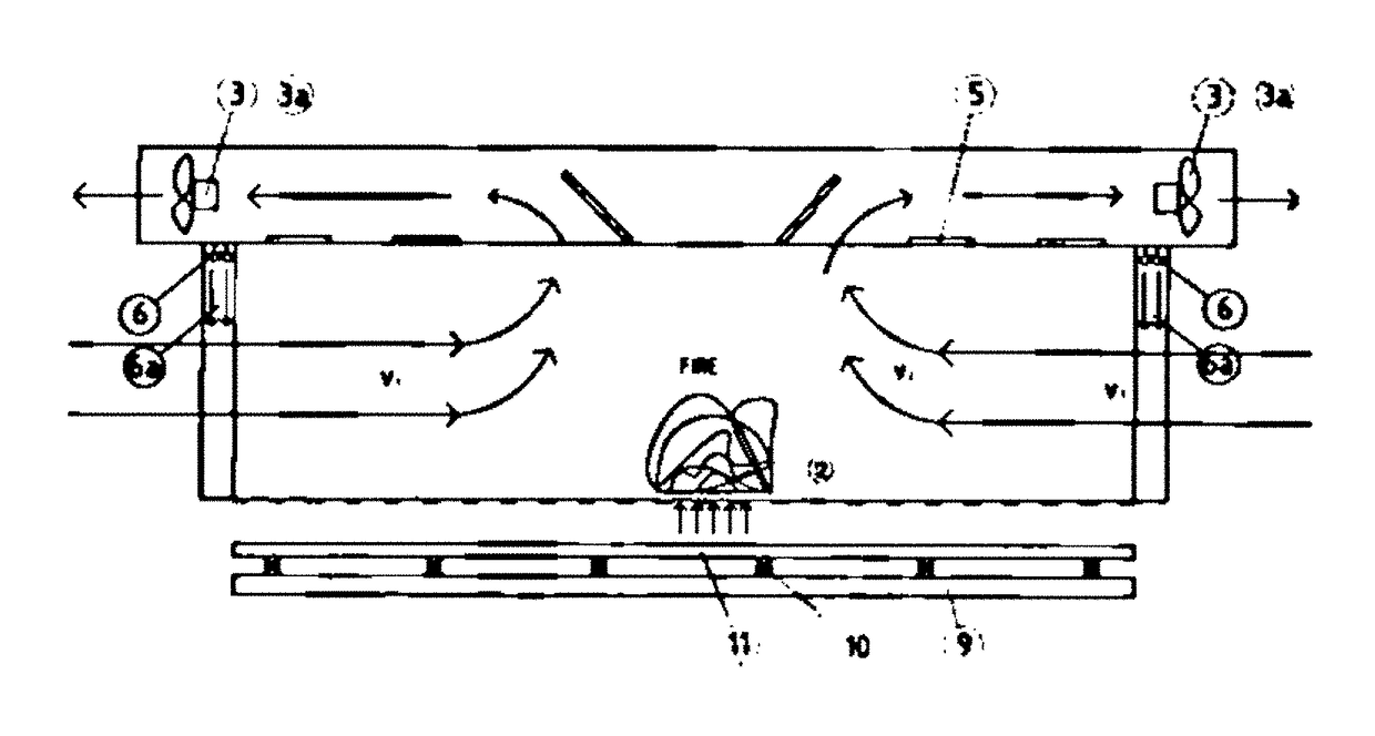
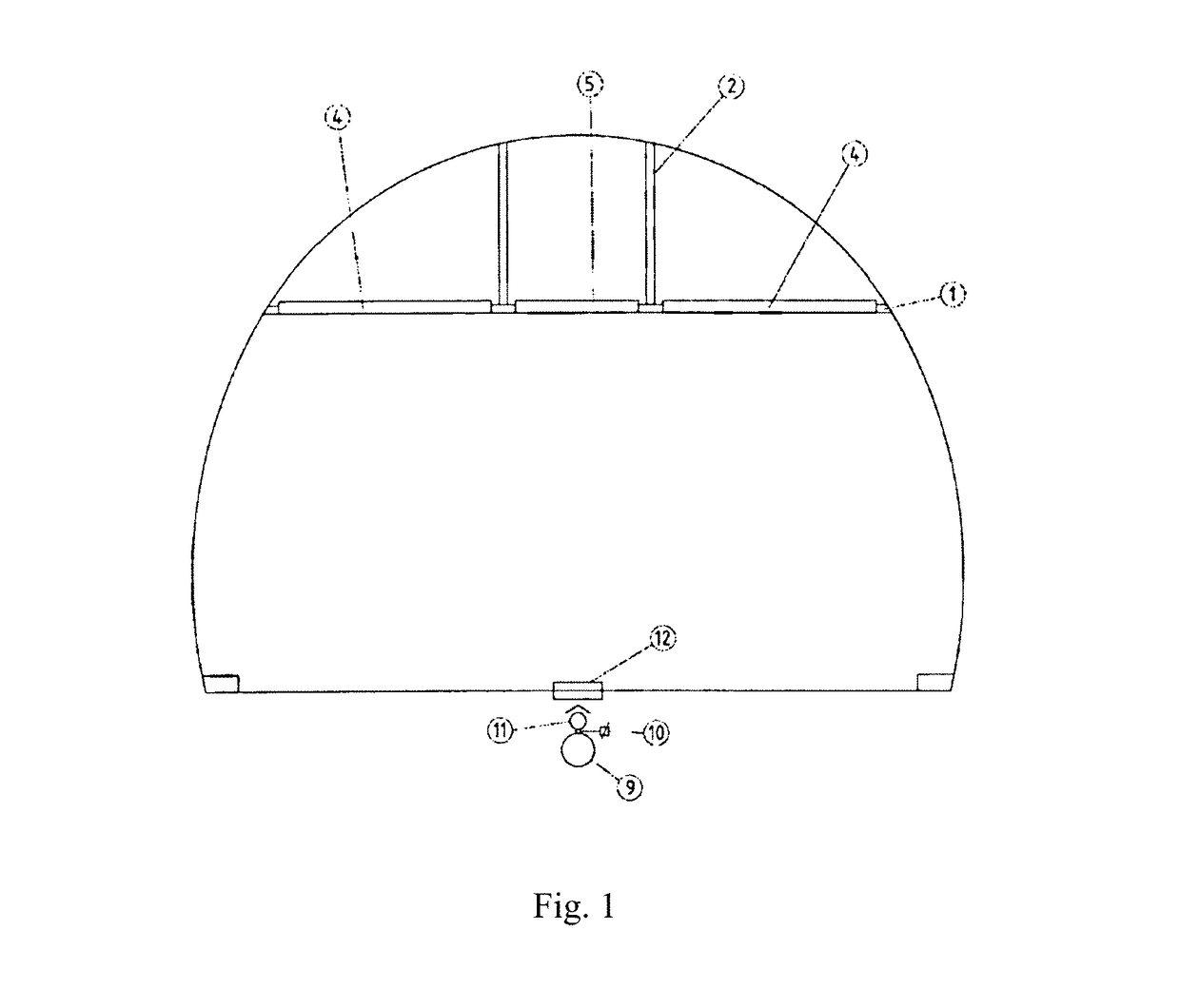
[0018]The tunnel ventilation system involves the use of a suspended ceiling with 2 partitions (2) above it, or 3 ducts with built-in fire-resistant flaps (4) and (5), the dimensions of which ensure a sufficient air intake velocity during aspiration and extend from one to the other lateral side of the duct, virtually from one to the other lateral wall of the tunnel. The flaps (4) in the lateral ducts open up along the longitudinal axis, and the flaps (5) in the middle duct along the axis perpendicular to the longitudinal axis of the duct. All flap drives are placed and can be maintained with the ventilation ducts also while traffic is in progress.

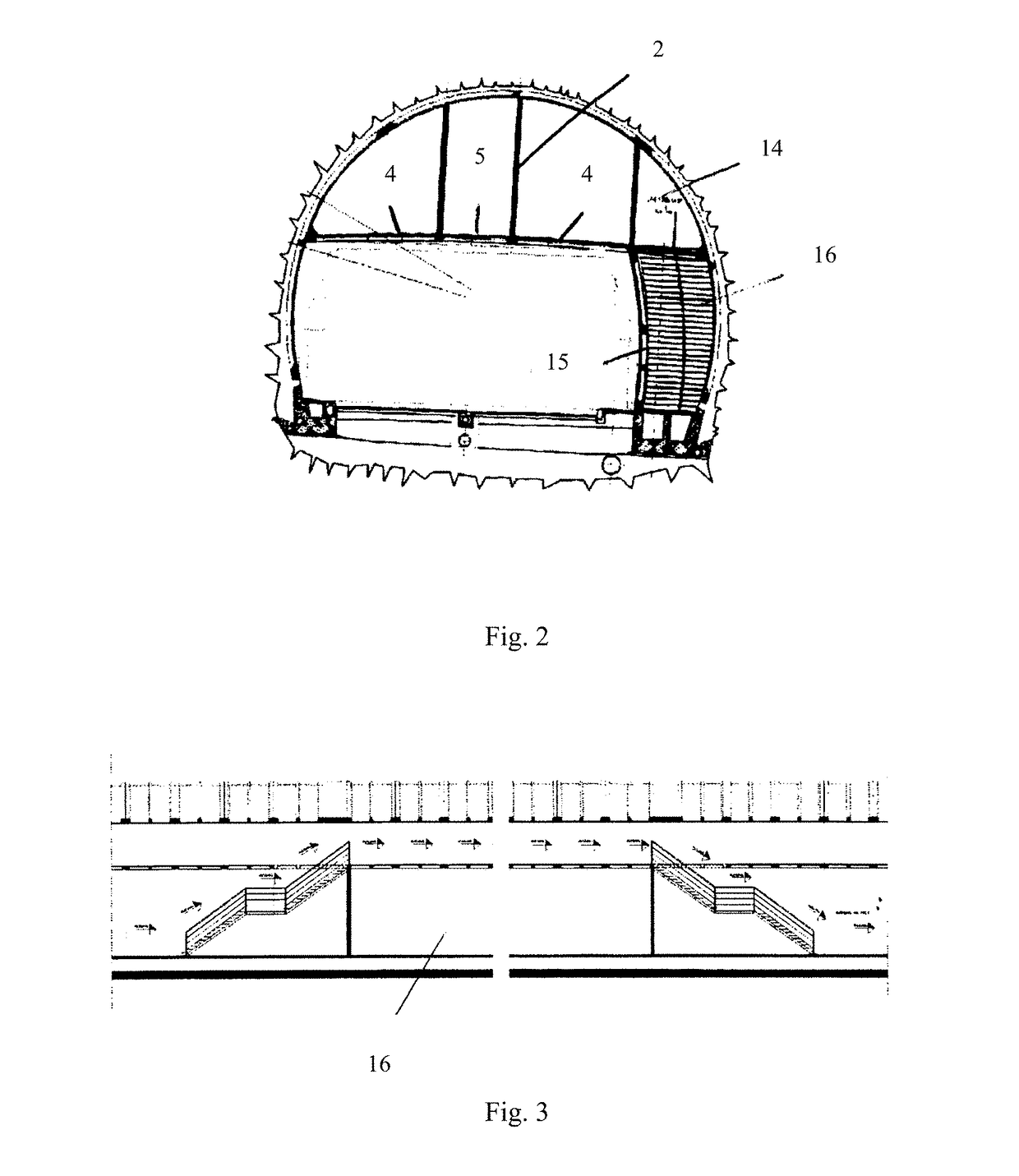
[0019]The tunnel ventilation system in normal and in fire conditions, where at a given height the tunnel is divided by a horizontal partition (1) into traffic and ventilation parts, where the system contains a lateral escape passage (16) accessed from the traffic part through a pressure door (15) with springs, where the ventilation part is p...


PUM


Abstract

A tunnel ventilation system located in an upper section of a tunnel has a ventilation section divided into two or three ventilation ducts. One or more of the ducts are connected to reversible fan units so the ducts can serve as either an air infeed or an air exhaust system. The ducts contain a series of remotely controlled flaps which can be opened to ventilate different tunnel zones or closed to isolate other parts of the tunnel. Air blowers at tunnel entrances create an air screen that prevents unintended air circulation into the tunnel. Heat, smoke and other sensors and a software control system enable the system to detect smoke and fire, then to isolate and control ventilation in the fire zone. A fire suppression system using low oxygen air or other fire suppression fluids to blanket and smother the fire operates in conjunction with the ventilation system.

Description

FIELD OF THE INVENTION[0001]This invention refers to the tunnel ventilation process in normal conditions and in fire conditions and to a tunnel ventilation system in such conditions designed to prevent a longitudinal air flow in the tunnel during a fire as well as to provide fire protection in long tunnels. The invention ensures a stationary air motion in the fire zone with simultaneous fire extinguishing to prevent the spread of fire and smoke in the tunnel outside the fire-affected zone.BACKGROUND OF THE INVENTION[0002]The problem appearing in tunnels, especially the longer ones, is how to ensure the removal of contaminated gas from the tunnel in an easy and efficient way, combined with quick and efficient fire extinguishing without a spread of smoke into the part of the tunnel not affected by fire. The Invention solves these technical problems by providing a stationary air flow in the tunnel applying a ventilation system and a tunnel ventilation process, where the ventilation sec...

Claims


Application Information

Patent Timeline
Patent Type & Authority Patents(United States)
IPC IPC(8): E21F1/00E21F1/08
CPCE21F1/003E21F1/08A62C3/0221E21F1/00
Inventor PAVETIC, IVORPAVETIC, SVIBOR
Owner PAVETIC JOSIP
Why Eureka
Try Eureka