Injection device

a technology of injection device and shield, which is applied in the direction of injection needles, intravenous devices, automatic syringes, etc., can solve the problems of inability to rigidly hold the syringe in the injection device, and the damage of the needle shield,

Active Publication Date: 2017-09-12
CILAG GMBH INT
View PDF810 Cites 18 Cited by
  • Summary
  • Abstract
  • Description
  • Claims
  • Application Information

AI Technical Summary

Benefits of technology

[0011]In this way, the syringe and its discharge nozzle can be protected against damage caused by rearward movement within the injection device.
[0015]In this way, the syringe can be easily inserted into the syringe carrier during manufacture whilst subsequently being rigidly held at its flange to prevent rearward movement.
[0018]In this way, movement of the syringe in the syringe carrier is damped and restricted such that the shock of an impact force is not transmitted along the syringe causing damage to the syringe.
[0022]In this way, the biasing means can be integrally moulded with the syringe carrier for ease of manufacture.
[0025]The discharge nozzle comprises a hypodermic needle and the syringe comprises a removable needle shield on the needle. In this embodiment, the syringe carrier is adapted to prevent rearward movement of the syringe so that the needle shield does not become removed from the syringe when an impact force is applied to the injection device. This prevents the discharge nozzle of the syringe becoming exposed to an non-sterile environment if, for example, the device is dropped onto a hard surface. In addition, the integrity seal of the discharge nozzle connecting to the syringe can be disturbed if rearward movement of the syringe occurs. The present invention overcomes this problem.

Problems solved by technology

In practice, the syringe may not be held rigidly in place within the injection device due, for example, to manufacturing tolerances in the syringe and injection device.
This is undesirable because the needle is exposed to an environment which may not be sterile.
The needle may also become damaged without the protection of the needle shield.

Method used


Image

  • Injection device
  • Injection device
  • Injection device

Examples


Embodiment Construction

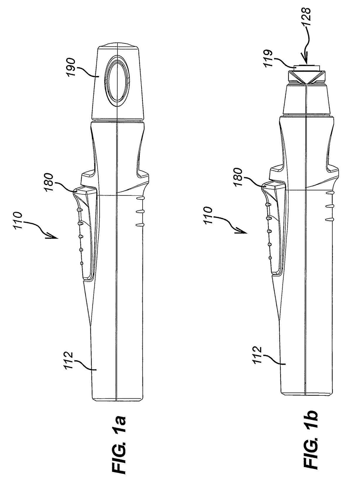
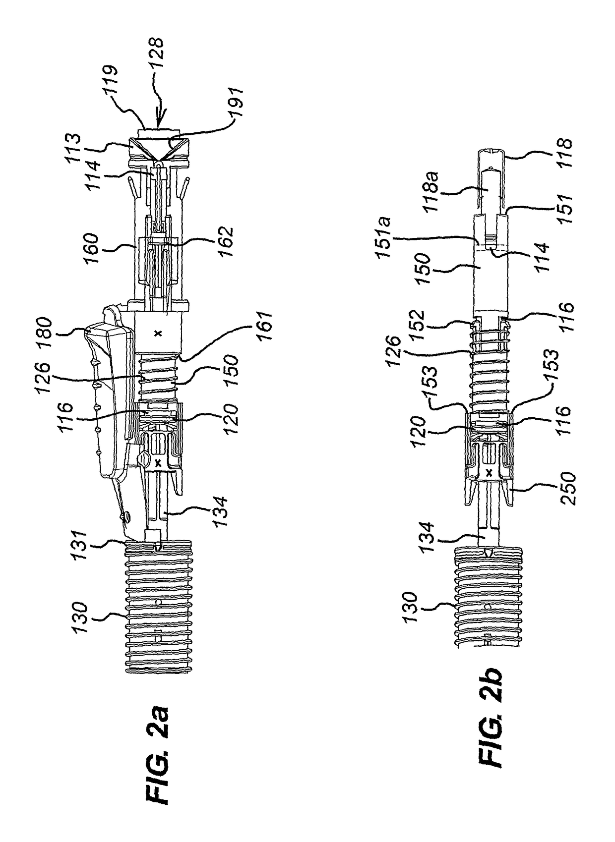
[0032]FIGS. 1a and 1b show an injection device 110, having an injection device housing 112. The injection device 110 has a removable cap 190. With the cap 190 removed, as shown in FIG. 2, the end of the housing 112 can be seen to have an exit aperture 128, through which the end of a sleeve 119 can emerge. The injection device 110 also has a trigger 180.

[0033]As shown in FIGS. 2a and 2b, the housing 112 contains a hypodermic syringe 114 of conventional type, including a syringe body 116 defining a reservoir and terminating at one end in a hypodermic needle (not shown) and at the other in a flange 120. The hypodermic needle is covered by a needle shield 118. The needle shield 118 is fixed inside the cap 190.

[0034]The syringe body 116 is of substantially constant diameter along the length of the reservoir, and is of significantly smaller diameter close to the end of the syringe which terminates in the hypodermic needle. A drive element 134 (syringe piston) acts through the bung of the ...


PUM


Abstract

An injection device 110 is described having a housing 112 that receives a syringe 114 having a needle 118, wherein the syringe is supported in a syringe carrier 150. The syringe 114 and syringe carrier 150 are biased by a return spring 126 from an extended position in which the needle 118 extends from the housing 112 through an exit aperture 128 to a retracted position in which it does not. A drive spring 130 acts via a drive to advance the syringe 114 from its retracted position to its extended position and discharge its contents through the needle 118 and a return spring 126, brought into play when the drive has reached a nominal return position, restores the syringe 114 to its retracted position. The syringe carrier 150 is designed to restrict rearward movement of the syringe so that the injection device is less prone to failure and damage to is components than prior art devices.

Description

FIELD OF THE INVENTION[0001]The present invention relates to an injection device of the type that receives a syringe, extends it through an exit aperture, discharges its contents and then retracts it automatically.BACKGROUND OF THE INVENTION[0002]Devices of this general description are shown in WO 95 / 35126 and EP-A-0 516 473 and tend to employ a drive spring and some form of release mechanism that releases the syringe from the influence of the drive spring once its contents are supposed to have been discharged, to allow it to be retracted by a return spring.[0003]Often, such injection devices are required to work with glass pre-filled syringes that were originally designed for manual use. Such glass syringes have a flange at their base to allow a user to grip the syringe and a needle through which the contents of the syringe can be ejected. Prior to use, the needle is generally covered with a needle shield which may be of plastic or rubber material. The needle shield itself may be c...

Claims


Application Information

Patent Timeline
Patent Type & Authority Patents(United States)
IPC IPC(8): A61M5/20A61M5/32
CPCA61M5/2033A61M5/3202A61M5/3204A61M5/326A61M2005/206A61M2005/208A61M2005/2013A61M5/31A61M5/315A61M5/20
Inventor CORRIGAN, JOSEPH PETER
Owner CILAG GMBH INT
Why Eureka
Try Eureka