Centrifuge with sample bucket having grooves and swing rotor for the same

a technology of swing rotor and sample bucket, which is applied in the direction of centrifuges, etc., can solve the problems of increasing the weight of the bucket, increasing the cost of the overall product, and the cylindrical portion held by the operator with one hand may easily slip, so as to reduce the stress applied to the sample container, prolong the lifespan and the effect of the replacement period

Active Publication Date: 2017-09-12
EPPENDORF HIMAC TECH CO LTD
View PDF8 Cites 5 Cited by
  • Summary
  • Abstract
  • Description
  • Claims
  • Application Information

AI Technical Summary

Benefits of technology

[0014]According to the invention, partial deformation of the sample container due to non-uniform support of the bucket seating surface can be suppressed and consequently the stress applied on the sample container can be reduced. Therefore, the lifespan and replacement period can be extended to achieve cost reduction. Furthermore, because the groove or rib provides an anti-slip effect, the effect of facilitating the opening and closing of the lid is achieved.

Problems solved by technology

However, because the thickness increases, this method has the disadvantage of increasing the weight of the bucket.
The increase of the load applied on the rotor body and the sample container itself has the problem that the sample container or the rotor body needs to be designed to be firm with use of a strong material so as to withstand the applied load, and consequently the overall product price rises.
Thus, the cylindrical portion held by the operator with one hand may easily slip when the operator opens or closes the lid.
If slip occurs during opening and closing of the lid, the vibration generated when the lid is opened may be transmitted to the sample to disturb the separation layers of the sample that has been separated.

Method used


Image

  • Centrifuge with sample bucket having grooves and swing rotor for the same
  • Centrifuge with sample bucket having grooves and swing rotor for the same
  • Centrifuge with sample bucket having grooves and swing rotor for the same

Examples


embodiment 1

[0028]Hereinafter, embodiments of the invention are described with reference to the figures. In the figures below, the same parts are assigned with the same reference numerals, and repeated descriptions will be omitted. Moreover, in this specification, the vertical and horizontal directions, axial direction, and longitudinal direction refer to the directions shown in the figures.

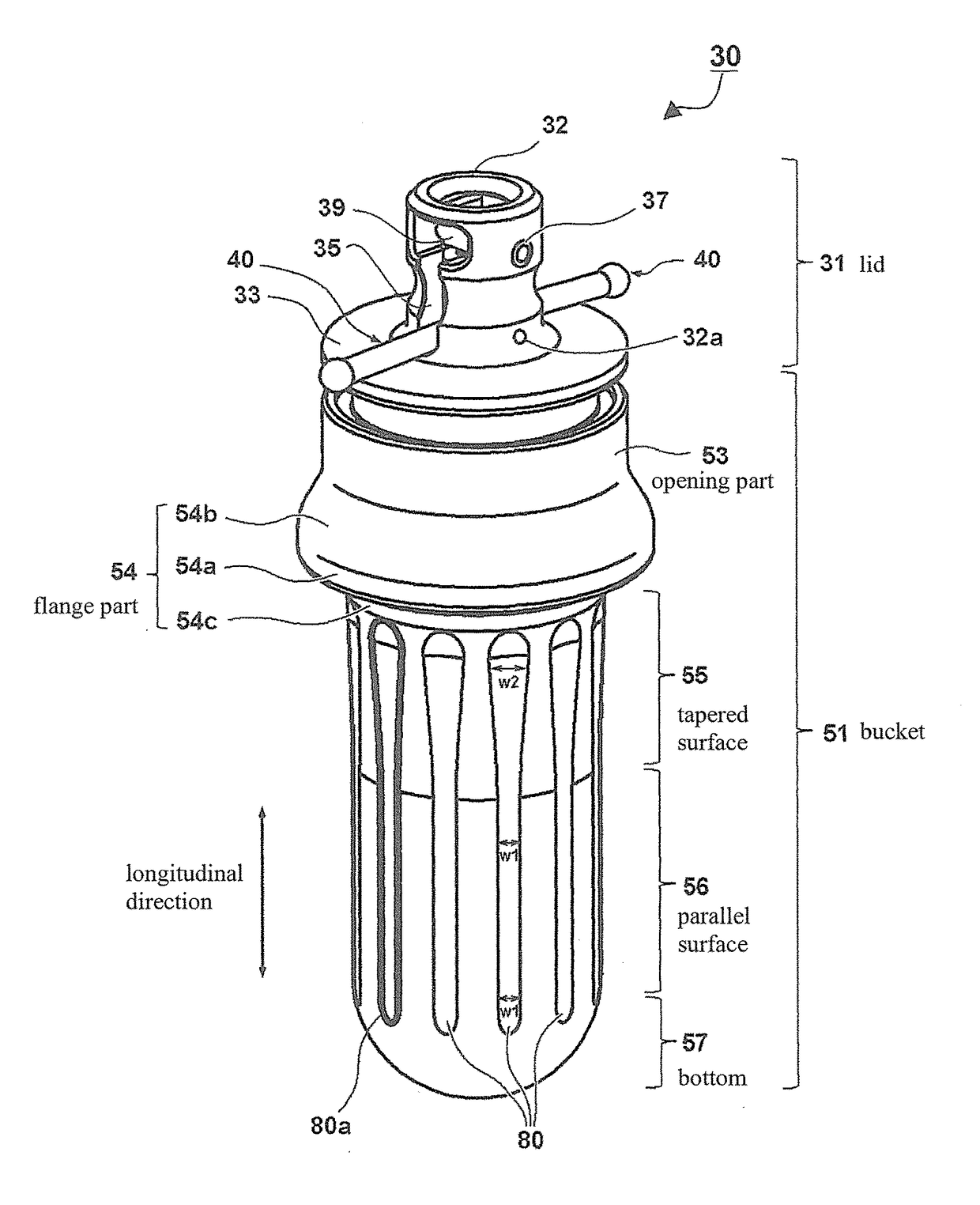
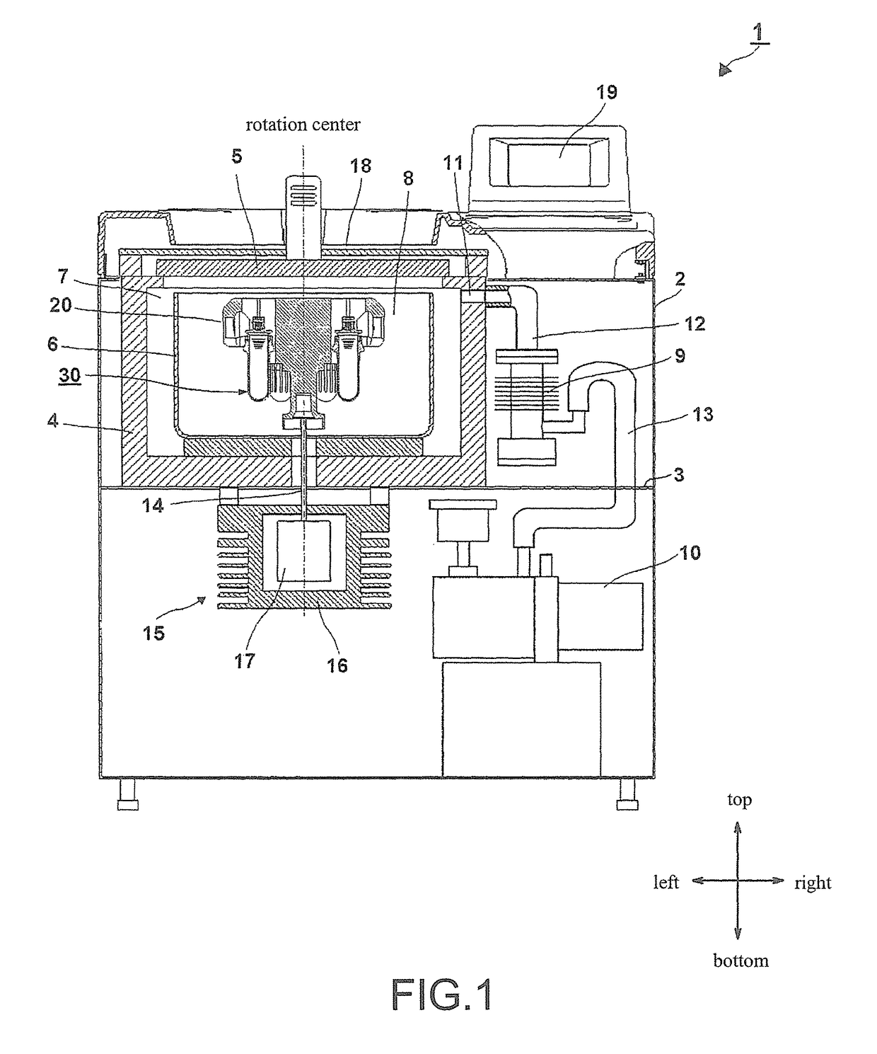
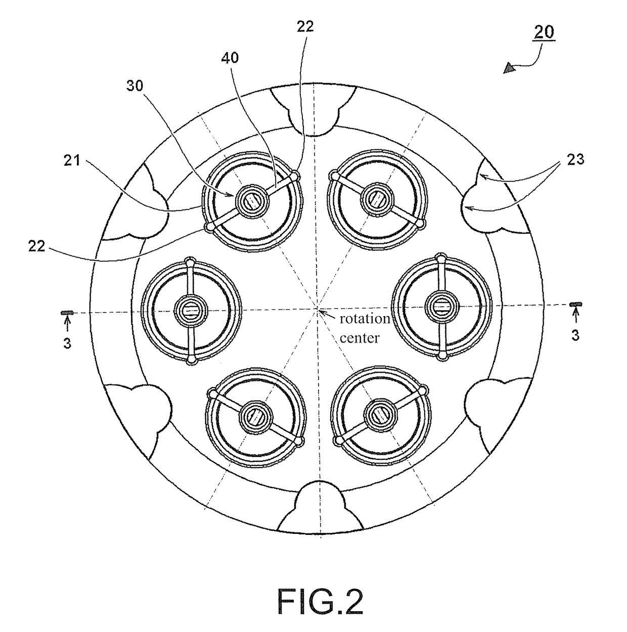
[0029]A centrifuge 1 is accommodated in a box-shaped case 2 that is made of sheet metal or plastic, and the interior of the case 2 is partitioned into an upper space and a lower space by a horizontal partition plate 3. A protective wall 4 is disposed inside the upper space. The protective wall 4 and a door 5 define a decompression chamber 7 where a bowl 6 is accommodated. Then, by closing the door 5, the decompression chamber 7 is sealed by a door packing (not shown). The bowl 6 has a cylindrical shape that is open on the top side and substantially closed on the bottom side. A rotor body 20, on which a plura...

embodiment 2

[0050]Next, the second embodiment of the invention is described with reference to FIG. 11. In FIG. 11, in contrast to the first embodiment, a plurality of ribs 180 having a convex shape are disposed on the cylindrical surface of a bucket 151. It is expected that it will be difficult to process such a shape by machine. Therefore, it is preferable to form the shape integrally by casting or forging. In this case, as compared with the bucket 51 of the first embodiment, instead of slightly reducing the outer diameter to thin the thickness (equivalent to 81 of FIG. 8), the ribs 180 are disposed to reduce the weight of the sample container 30 and improve the rigidity against bending. The ribs 180 are arranged at equal intervals in the circumferential direction of the bucket 151 and are disposed not to interfere with the adjacent ribs 180. Here, twelve ribs 180 are formed. The shape of the front end of the convex rib 180 (an upper end 180b and a lower end 180c) is a continuous curved surfac...


PUM


Abstract

A centrifuge and a rotor thereof are provided. The centrifuge performs centrifugation in a state where the sample container is swung by rotation and seated in a cutout part of a rotor body. The sample container includes a bucket accommodating a container filled with a sample, and a lid for sealing the bucket and having a rotation shaft. Grooves extending in the longitudinal direction are formed on the outer peripheral surface of the bucket on the bottom side with respect to a seating surface of the bucket. The grooves are arranged at equal intervals in the circumferential direction. Formation of the grooves can prevent increasing the weight of the bucket and realize a highly rigid sample container that can withstand deformation.

Description

CROSS-REFERENCE TO RELATED APPLICATION[0001]This application claims the priority benefit of Japan application serial no. 2015-014392, filed on Jan. 28, 2015. The entirety of the above-mentioned patent application is hereby incorporated by reference herein and made a part of this specification.BACKGROUND OF THE INVENTION[0002]Field of the Invention[0003]The invention relates to a centrifuge for separating a sample in the fields of medicine, pharmacy, genetic engineering, biotechnology, and so on, and particularly relates to securing strength and enhancing operability through improvement of the rigidity of a sample container for the centrifuge with a swing type rotor.[0004]Description of Related Art[0005]A centrifuge is a device, which includes a rotor capable of accommodating a plurality of sample containers filled with samples therein and a driving means, such as a motor, rotationally driving the rotor in a rotor chamber, and rotates the rotor at a high speed to apply a centrifugal ...

Claims


Application Information

Patent Timeline
Patent Type & Authority Patents(United States)
IPC IPC(8): B04B5/04
CPCB04B5/0421B04B2005/0435
Inventor SATO, JUNNEMOTO, KENICHI
Owner EPPENDORF HIMAC TECH CO LTD
Why Eureka
Try Eureka