Centrifuge and swing rotor for centrifuge
a centrifuge and swing rotor technology, applied in the field of centrifuges, can solve the problems of increasing the weight of the bucket, increasing the cost of the product, and the cylindrical portion held by the operator with one hand may easily slip, so as to reduce the stress applied to the sample container, prolong the lifespan and the effect of replacement period
- Summary
- Abstract
- Description
- Claims
- Application Information
AI Technical Summary
Benefits of technology
Problems solved by technology
Method used
Image
Examples
embodiment 1
[0028]Hereinafter, embodiments of the invention are described with reference to the figures. In the figures below, the same parts are assigned with the same reference numerals, and repeated descriptions will be omitted. Moreover, in this specification, the vertical and horizontal directions, axial direction, and longitudinal direction refer to the directions shown in the figures.
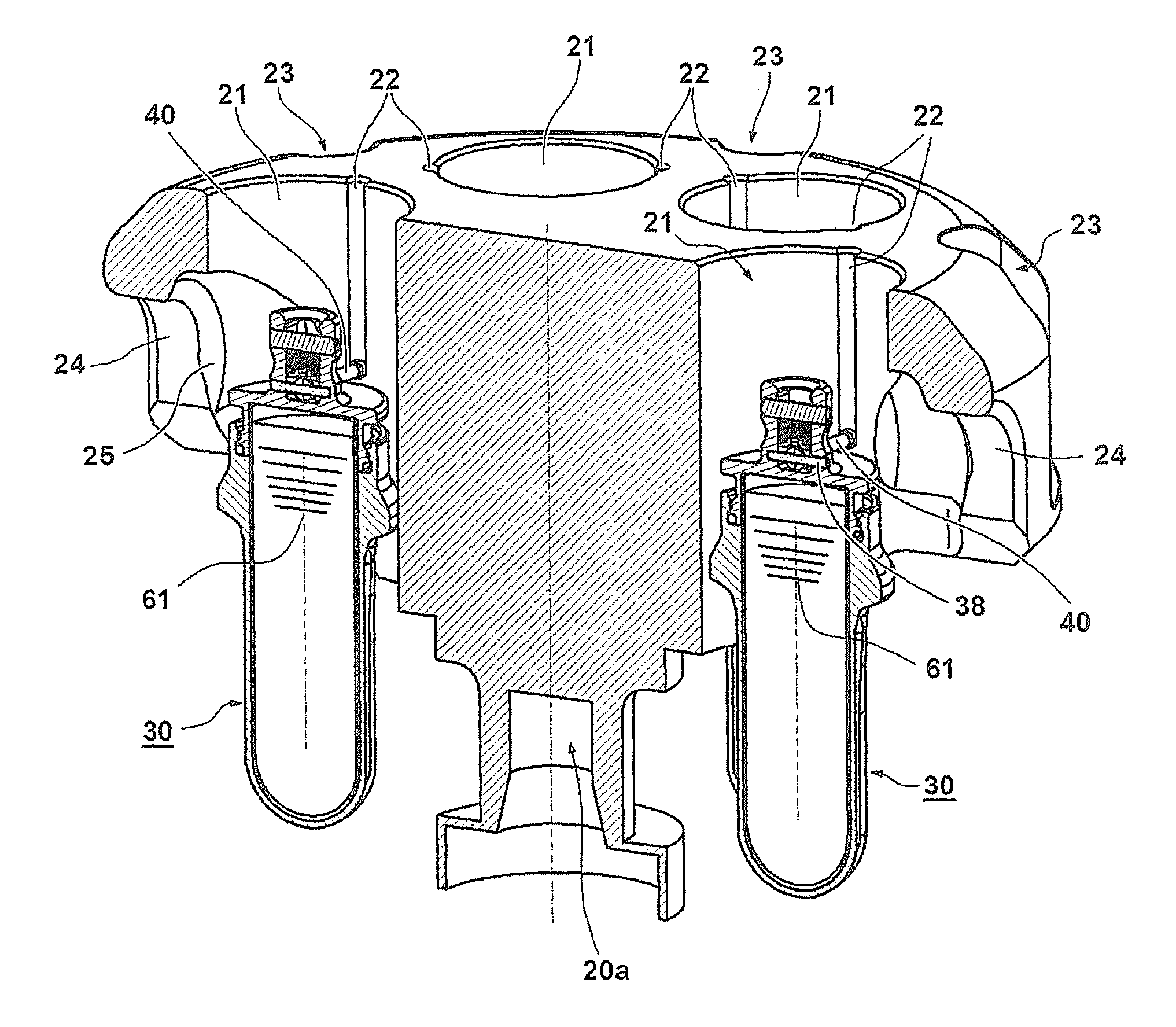
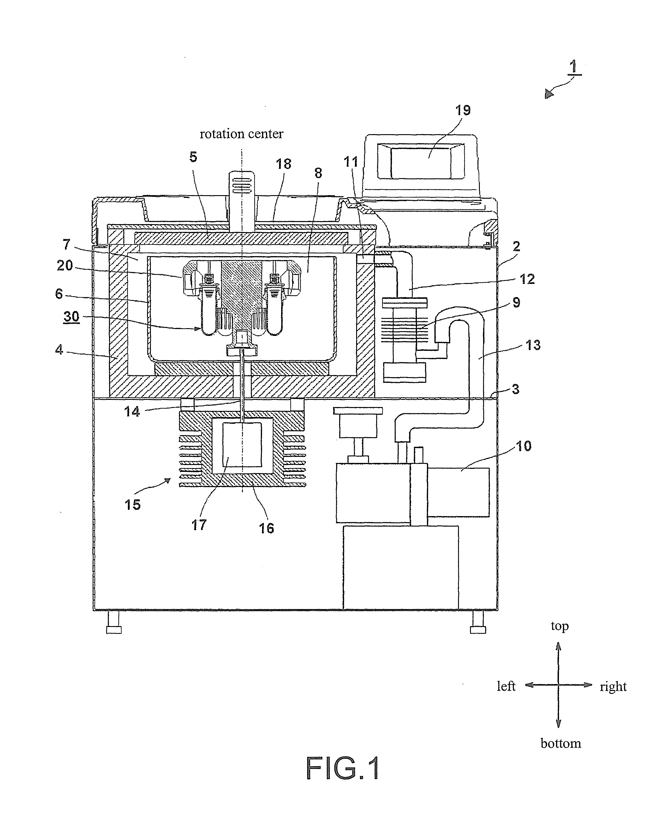
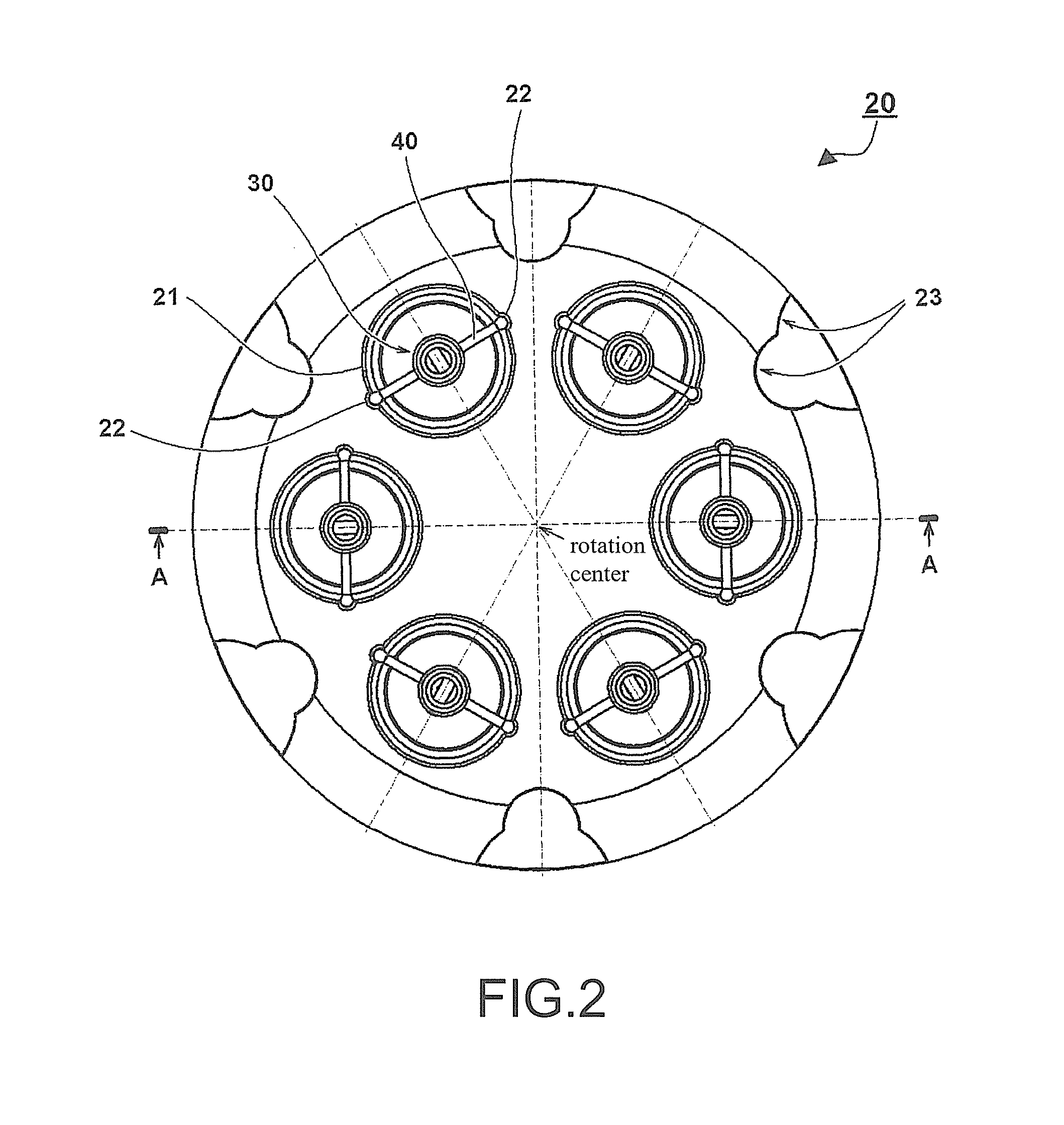
[0029]A centrifuge 1 is accommodated in a box-shaped case 2 that is made of sheet metal or plastic, and the interior of the case 2 is partitioned into an upper space and a lower space by a horizontal partition plate 3. A protective wall 4 is disposed inside the upper space. The protective wall 4 and a door 5 define a decompression chamber 7 where a bowl 6 is accommodated. Then, by closing the door 5, the decompression chamber 7 is sealed by a door packing (not shown). The bowl 6 has a cylindrical shape that is open on the top side and substantially closed on the bottom side. A rotor body 20, on which a plura...
embodiment 2
[0050]Next, the second embodiment of the invention is described with reference to FIG. 11. In FIG. 11, in contrast to the first embodiment, a plurality of ribs 180 having a convex shape are disposed on the cylindrical surface of a bucket 151. It is expected that it will be difficult to process such a shape by machine. Therefore, it is preferable to form the shape integrally by casting or forging. In this case, as compared with the bucket 51 of the first embodiment, instead of slightly reducing the outer diameter to thin the thickness (equivalent to 81 of FIG. 8), the ribs 180 are disposed to reduce the weight of the sample container 30 and improve the rigidity against bending. The ribs 180 are arranged at equal intervals in the circumferential direction of the bucket 151 and are disposed not to interfere with the adjacent ribs 180. Here, twelve ribs 180 are formed. The shape of the front end of the convex rib 180 (an upper end 180b and a lower end 180c) is a continuous curved surfac...
PUM
 Abstract
Description
Claims
Application Information
 - R&D
- Intellectual Property
- Life Sciences
- Materials
- Tech Scout
- Unparalleled Data Quality
- Higher Quality Content
- 60% Fewer Hallucinations
Browse by: Latest US Patents, China's latest patents, Technical Efficacy Thesaurus, Application Domain, Technology Topic, Popular Technical Reports.
© 2025 PatSnap. All rights reserved.Legal|Privacy policy|Modern Slavery Act Transparency Statement|Sitemap|About US| Contact US: help@patsnap.com


