Power harvest architecture for near field communication devices

a technology of near field communication and power harvesting, which is applied in the direction of near-field transmission, transmission, electric devices, etc., can solve the problems of inaccurate wakeup sequence, dv/v violation, overloading of nfc readers,

a technology of near field communication and power harvesting, which is applied in the direction of near-field transmission, transmission, electric devices, etc., can solve the problems of inaccurate wakeup sequence, dv/v violation, overloading of nfc readers,

US9762292B2Active Publication Date: 2017-09-12TEXAS INSTR INC

Image

  • Power harvest architecture for near field communication devices
  • Power harvest architecture for near field communication devices
  • Power harvest architecture for near field communication devices

Examples


Embodiment Construction

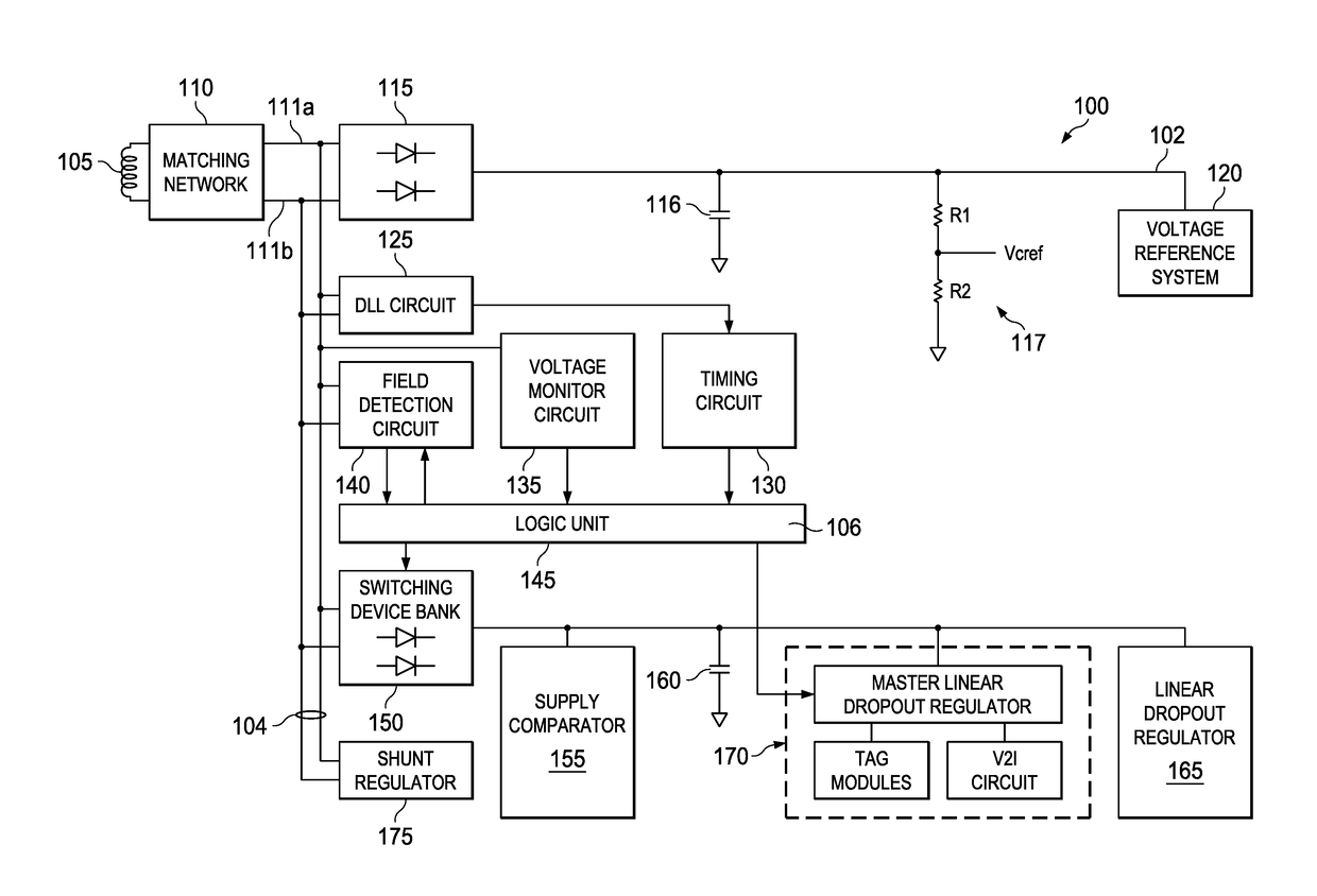
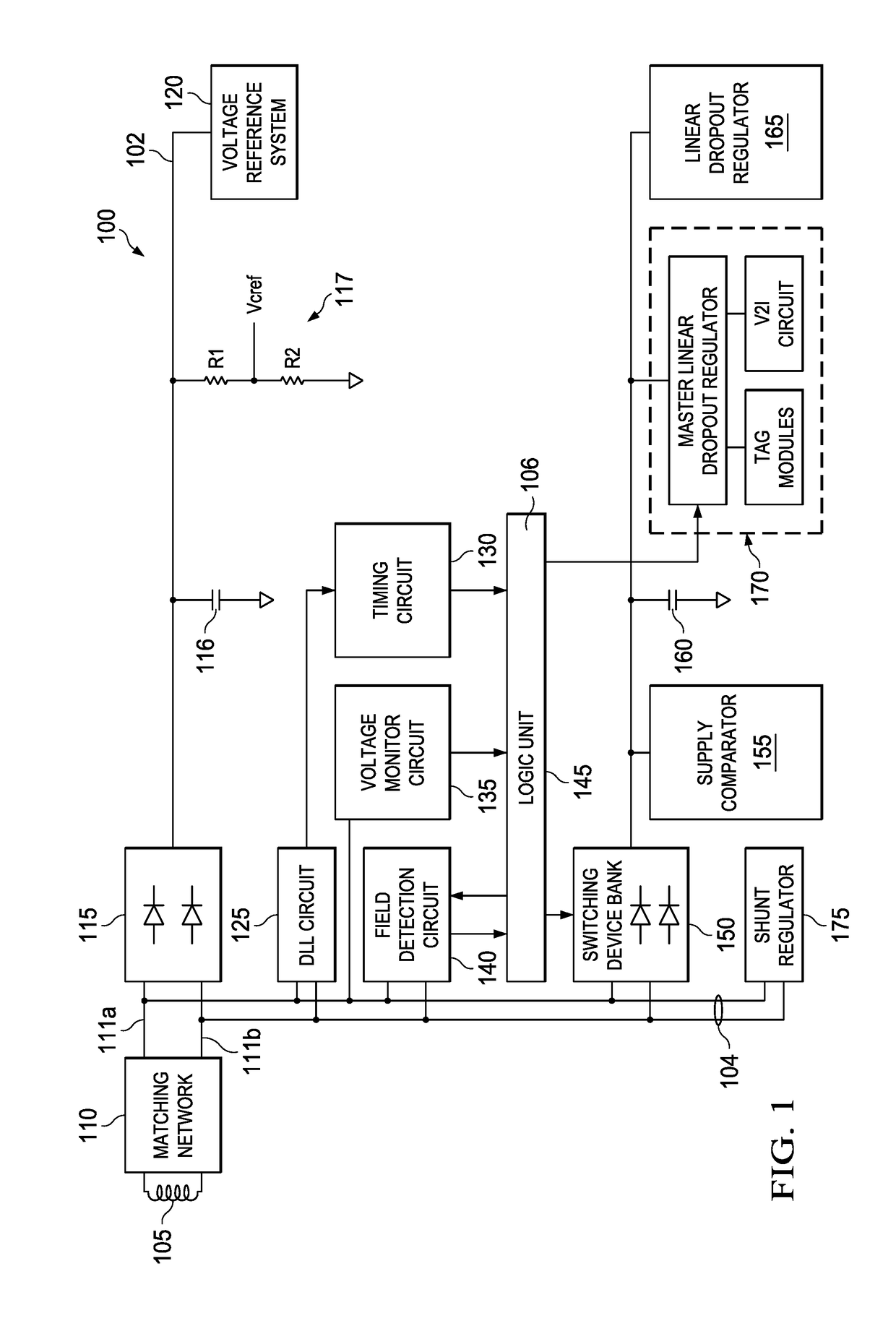
[0014]FIG. 1 illustrates a schematic of an electronic communication device 100 according to an embodiment. The electronic communication device 100 is one of RF (radio frequency) device, NFC (near field communication) device or any field communication device. The electronic communication device 100 includes an antenna 105. The antenna 105 is coupled to a matching network 110 which is further coupled to a first tag pin 111a and a second tag pin 111b (differential tag pins 111a and 111b). A half wave rectifier 115 is coupled to the differential tag pins 111a and 111b. A capacitor 116, a voltage divider circuit 117 and a voltage reference system 120 are coupled to the half wave rectifier 115. The voltage divider circuit 117 includes resistor R1 and resistor R2. One end of resistor R2 is coupled to ground. A DLL (Digital locked loop) circuit 125 is coupled to the differential tag pins 111a and 111b. A timing circuit 130 is coupled to the DLL circuit 125. A voltage monitor circuit 135 is ...


PUM


Abstract

A method of charging a power harvested supply in an electronic communication device, which can be an NFC (near field communication) device. The power harvested supply in the electronic communication device is charged without causing dV / V violation and avoids false wake up. An RF (radio frequency) field is received at the antenna of the electronic communication device. A differential voltage is generated from the RF field at a first tag pin and a second tag pin of the electronic communication device. A bandgap reference voltage and a reference current are generated in response to the differential voltage. A shunt current is generated in response to the differential voltage and the bandgap reference voltage. A bank of switching devices is activated if the shunt current is more than the reference current.

Description

TECHNICAL FIELD[0001]Embodiments of the disclosure relate to near field communication (NFC) devices and more particularly to an improved power harvest architecture for NFC devices.BACKGROUND[0002]NFC is a 13.56 MHz carrier based secure communication technology which is used in personal ID, money transaction etc. It is to be noted that NFC communication technology works on the same principle as RF communication technology. Hence, the NFC devices (readers / tags) can interchangeably interact with RF devices (readers / tags). An NFC system includes an NFC tag that contains information and an NFC reader that reads information from the NFC tag. An NFC tag can be an active NFC tag or a passive NFC tag. An active NFC tag generates its own magnetic field to interact with an NFC reader. The passive NFC tag utilizes the magnetic field or radio frequency (RF) field generated by an NFC reader for operation.[0003]When the magnetic field of the NFC reader is incident on the antenna of the passive NFC...

Claims


Application Information

Patent Timeline
12 Sep 2017
Publication
US9762292B2
IPC
H04B5/00
CPC
H04B5/0037
Inventors
MANIAN, SRIKANTH; DARWHEKAR, YOGESH