Modular air filter housing

a module and air filter technology, applied in the direction of separation process, dispersed particle separation, chemistry apparatus and processes, etc., can solve the problems that the industry lacks efficient gasket seals for high-speed frames, and achieves high efficiency, increased motor horsepower, and high efficiency.

Active Publication Date: 2017-09-19
CARTER SCOTT
View PDF32 Cites 121 Cited by
  • Summary
  • Abstract
  • Description
  • Claims
  • Application Information

AI Technical Summary

Benefits of technology

[0013]The performance of the double cartridge frame opens up many design opportunities that currently are not available with the commonly supplied filter holding frames and housings. High velocity frames with an efficient gasket seal have not been available in the industry. With the evolving technology of new higher efficiency filter medias, there has been a push by most all HVAC filter manufacturers to produce low pressure drop high efficiency filters, especially in the common 4″ depth in lieu of the standard 12″ to save labor, freight, manufacturing materials and disposal cost. The filter frames take full advantage of this technology to a level not conceived by the industry.
[0016]The option of higher efficiency filters in standard units, not currently offered, without dramatically effecting blower redesign and increased motor horsepower.
[0017]The use of high efficiency prefilters in air conditioning applications allowing the units to remain clean requiring less maintenance and chemicals commonly used, such as acids and alkalines, while running more efficiently and reducing energy.
[0020]The potential design of high velocity air conditioning units which could decrease the overall cabinet height and / or width of an entire unit for limited space applications.
[0022]The overall benefits of this product have the potential to impact many segments throughout the air filter industry. The markets affected would include and not be limited to the manufacturers of air conditioning and heating units; process equipment OEM's of all kinds including for food and bottling equipment, air compressors, coolers, engine and motor intakes, gas turbines; outside air installations using fans, make-up air units, and intake hoods; foremarket and aftermarket filter housings; etc. The availability of a product that would be beneficial in just one area would be considerable with such a large market potential. However, a product that would significantly reduce waste storage, transfer and landfill requirements; energy; cleaning chemicals; shipping cost; and labor is unprecedented.

Problems solved by technology

High velocity frames with an efficient gasket seal have not been available in the industry.

Method used


Image

  • Modular air filter housing
  • Modular air filter housing
  • Modular air filter housing

Examples


Embodiment Construction

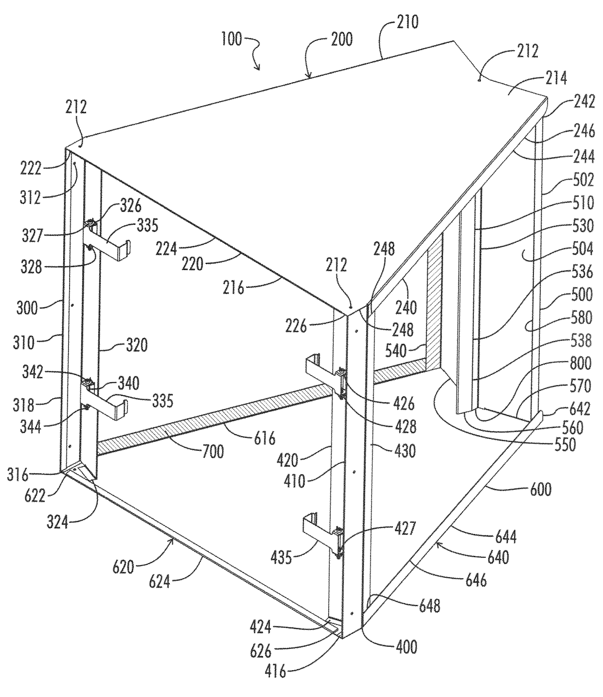
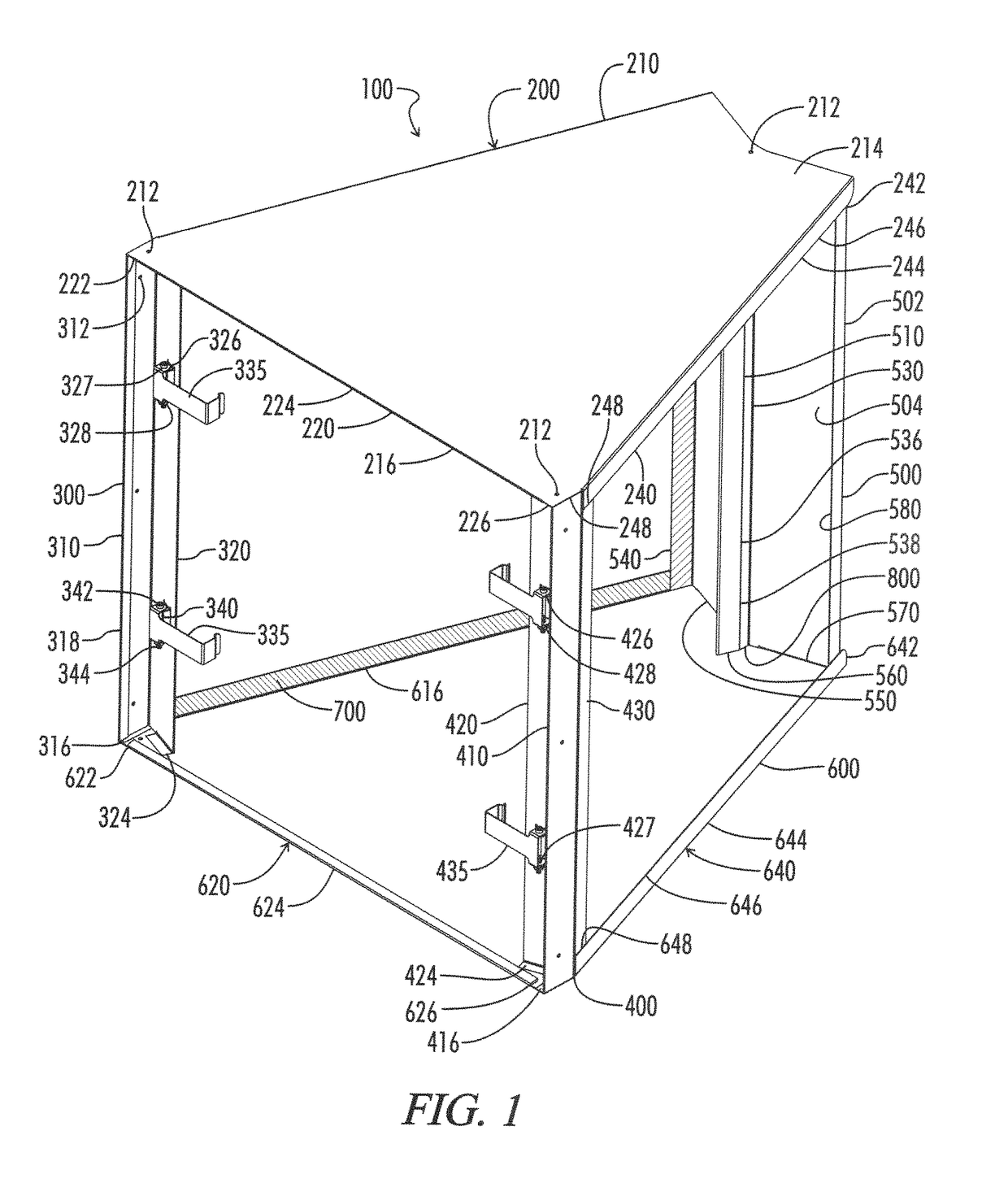
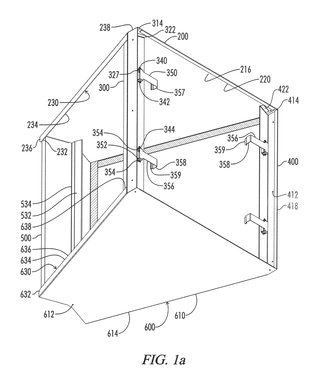
[0047]As shown in FIGS. 1 through 20 of the drawings, one exemplary embodiment of the present invention is generally shown as an air filter module 100. FIG. 8 shows how the air filter module 100 shown is designed for housing a double set of matching air filters 10. FIG. 9 shows how each air filter 10 includes a filter frame 12 housing a filter media 14. The filter frame 12 has a height 20, width 22, and depth 24. The filter media 14 is typically a pleated fabric or mesh with different available characteristics as is known in the art. FIGS. 1 through 7 show a first embodiment, and FIGS. 12 through 20 show a second embodiment with the embodiments sharing some similar characteristics.

[0048]Returning to FIGS. 1 through 20, the air filter module 100 is made from a top plate 200 mounted to three vertical pieces including a left front corner 300, right front corner 400, and back wall 500 which are all then connected to the bottom plate 600. The filters 10 are sealing engaged inside the air...


PUM

PropertyMeasurementUnit
velocityaaaaaaaaaa
pressure dropsaaaaaaaaaa
timeaaaaaaaaaa

Abstract

An air filter module for modularly mounting angled air filters. The module includes a top plate, bottom plate, left and right front corners with the corners defining perpendicular side walls, angled filter end retention walls, angled side walls, and a back wall with angled side walls, parallel end retention walls, and a positioning guide. The positioning guide is constructed from clips or a guide face and an inner side positioning wall.

Description

CROSS-REFERENCE TO RELATED APPLICATIONS[0001]This application claims priority to and is a continuation-in-part of U.S. patent application Ser. No. 14 / 637,042, filed on Mar. 13, 2015 entitled MODULAR AIR FILTER HOUSING, which is a continuation-in-part of U.S. patent application Ser. No. 29 / 448,658, filed on Mar. 13, 2013 entitled AIR FILTER HOUSING and U.S. patent application Ser. No. 29 / 471,889, filed on Nov. 6, 2013 entitled ANGLED BIFILTER HOUSING which are hereby incorporated by reference in their entirety.STATEMENT REGARDING FEDERALLY SPONSORED RESEARCH OR DEVELOPMENT[0002]Not Applicable.REFERENCE TO A MICROFICHE APPENDIX[0003]Not Applicable.RESERVATION OF RIGHTS[0004]A portion of the disclosure of this patent document contains material which is subject to intellectual property rights such as but not limited to copyright, trademark, and / or trade dress protection. The owner has no objection to the facsimile reproduction by anyone of the patent document or the patent disclosure as...

Claims


Application Information

Patent Timeline
Patent Type & Authority Patents(United States)
IPC IPC(8): B01D46/00B01D46/12
CPCB01D46/0005B01D46/002B01D46/125B01D46/121B01D46/58
Inventor CARTER, SCOTT
Owner CARTER SCOTT
Why Eureka
Try Eureka