System and method for identifying and controlling an electrosurgical apparatus

a technology of electrosurgical equipment and electrosurgical equipment, which is applied in the field of electrosurgical equipment and electrosurgical systems, can solve the problems of large volume of noxious smoke, collateral damage to surrounding healthy tissue, and relative slowness, and achieve the effect of ensuring optimum performance, safety and effectiveness

Active Publication Date: 2017-09-26
BOVIE MEDICAL CORP
View PDF113 Cites 109 Cited by
  • Summary
  • Abstract
  • Description
  • Claims
  • Application Information

AI Technical Summary

Benefits of technology

[0015]In one aspect of the present disclosure, an automatic applicator identifier is used to communicate between the apparatus or applicator and a generator unit, automatically presetting various values. These values may be stored in a one-wire serial memory storage device located in the applicator. Communication from the applicator to the generator unit of these values is affected by a one-wire serial communication protocol. It is to be appreciated that the serial communication protocol may be bidirectional, i.e., data may be read from the one-wire serial memory storage device and written to the one-wire serial memory storage device. This information can be transferred over a direct electrical path through the connector that attaches the applicator to the generator unit, or instead by a wireless link. Communication of these preset values is transferred from the applicator to the generator unit upon power-up initialization of the generator unit, whenever the generator unit is reset, or when requested by the generator unit. The communication link can be encrypted to prevent unauthorized modification of the preset values. The automatic applicator identifier can also provide unique device identification and traceability.
[0018]The automatic applicator identifier permits a general purpose adaptable interface between the applicator and generator unit so that a single generator unit can be used with a wide variety of applicator types, yet maintain optimum performance, safety, and effectiveness.

Problems solved by technology

In the latter example, the process can be relatively slow, generate large volumes of noxious smoke with vaporized and charred tissue, and may cause collateral damage to surrounding healthy tissue when high power electrosurgical energy is used.
Precision accuracy can also be a problem, due to the width of the plasma beam.
Those designed for a specific task may have limitations with regard to maximum power and / or gas flow rate, as in the case of plasma-beam applicators.
Also, there may be changes in the characteristics of the applicator with prolonged use, affecting its safety and effectiveness.
Finally, some applicators that are disposable cannot be re-sterilized and its use must be limited to a single procedure.

Method used


Image

  • System and method for identifying and controlling an electrosurgical apparatus
  • System and method for identifying and controlling an electrosurgical apparatus
  • System and method for identifying and controlling an electrosurgical apparatus

Examples


Embodiment Construction

[0033]Preferred embodiments of the present disclosure will be described hereinbelow with reference to the accompanying drawings. In the following description, well-known functions or constructions are not described in detail to avoid obscuring the present disclosure in unnecessary detail. In the drawings and in the description which follow, the term “proximal”, as is traditional, will refer to the end of the device, e.g., instrument, apparatus, applicator, handpiece, forceps, etc., which is closer to the user, while the term “distal” will refer to the end which is further from the user. Herein, the phrase “coupled” is defined to mean directly connected to or indirectly connected with through one or more intermediate components. Such intermediate components may include both hardware and software based components.

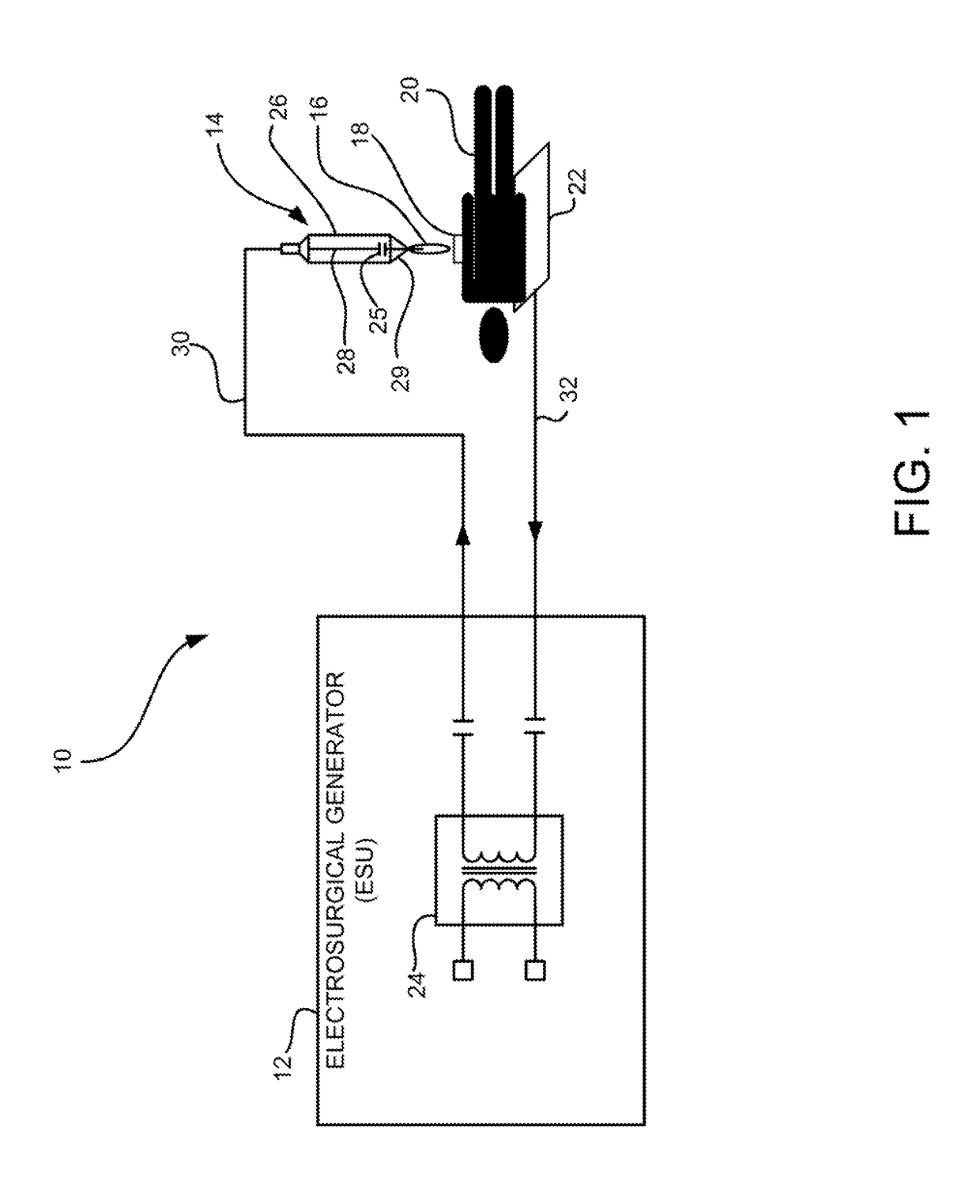
[0034]FIG. 1 shows an exemplary monopolar electrosurgical system generally indicated as 10 comprising an electrosurgical generator (ESU) generally indicated as 12 to generate...


PUM


Abstract

An electrosurgical apparatus including an automatic applicator identifier used to communicate between an applicator and a generator unit, automatically presetting various values, is provided. These values may be stored in a one-wire serial memory storage device located in the applicator or connector coupled to the applicator. Communication from the applicator to the generator unit of these values is affected by a one-wire serial communication protocol. This information can be transferred over a direct electrical path through the connector that attaches that applicator to the generator unit, or instead by a wireless link.

Description

PRIORITY[0001]This application is a continuation-in-part application of U.S. application Ser. No. 13 / 802,572 filed Mar. 13, 2013, which is a continuation-in-part application of U.S. application Ser. No. 13 / 289,060 filed Nov. 4, 2011, which claims priority on U.S. Provisional Patent Appl. No. 61 / 411,174, filed Nov. 8, 2010, the content of all of which are hereby incorporated by reference in their entireties.[0002]This application is also a continuation-in-part application of U.S. application Ser. No. 13 / 802,227 filed Mar. 13, 2013, which claims priority on U.S. Provisional Patent Appl. No. 61 / 667,213, filed Jul. 2, 2012 and U.S. Provisional Patent Appl. No. 61 / 716,688, filed Oct. 22, 2012, the content of all of which are hereby incorporated by reference in their entireties.BACKGROUND[0003]Field[0004]The present disclosure relates generally to electrosurgery and electrosurgical systems and apparatuses, and more particularly, to an electrosurgical apparatus including an automatic appli...

Claims


Application Information

Patent Timeline
Patent Type & Authority Patents(United States)
IPC IPC(8): A61B18/14A61B18/04A61B90/00A61B18/12A61B18/00A61B17/00A61B17/3209
CPCA61B18/1402A61B18/042A61B2018/00589A61B2018/00607A61B2018/00946A61B2018/00988A61B2018/1286A61B2018/1475A61B2090/0811A61B17/3209A61B2017/00221A61B2018/00178
Inventor ZORAN, ARIKKONESKY, GREGORY A.
Owner BOVIE MEDICAL CORP
Why Eureka
Try Eureka