System for identifying the magnitude and position of a load within a weight area of a beam

Inactive Publication Date: 2017-09-26
UNITED STATES OF AMERICA THE AS REPRESENTED BY THE SEC OF THE ARMY
View PDF2 Cites 17 Cited by
  • Summary
  • Abstract
  • Description
  • Claims
  • Application Information

AI Technical Summary

Problems solved by technology

Overloading the load cell can lead to damage.

Method used


Image

  • System for identifying the magnitude and position of a load within a weight area of a beam
  • System for identifying the magnitude and position of a load within a weight area of a beam
  • System for identifying the magnitude and position of a load within a weight area of a beam

Examples


Embodiment Construction

[0151]In the description herein with respect to the drawings, any reference to direction is purely informative and is employed for ease of reference. It is not intended as limiting the scope of the claims herein.

[0152]The deflection plate or anchor arm plate of the present invention is for use in the M16 Heavy Mobile Dynamometer Vehicle (manufactured by Barnes and Reinecke in the late 1970's) and the M18 Medium Mobile Dynamometer Vehicle (manufactured also by Barnes and Reinecke, in the late 1980's). These vehicles are designed for testing power drawbar effect and resistance to towing characteristics of tracked and wheeled vehicles.

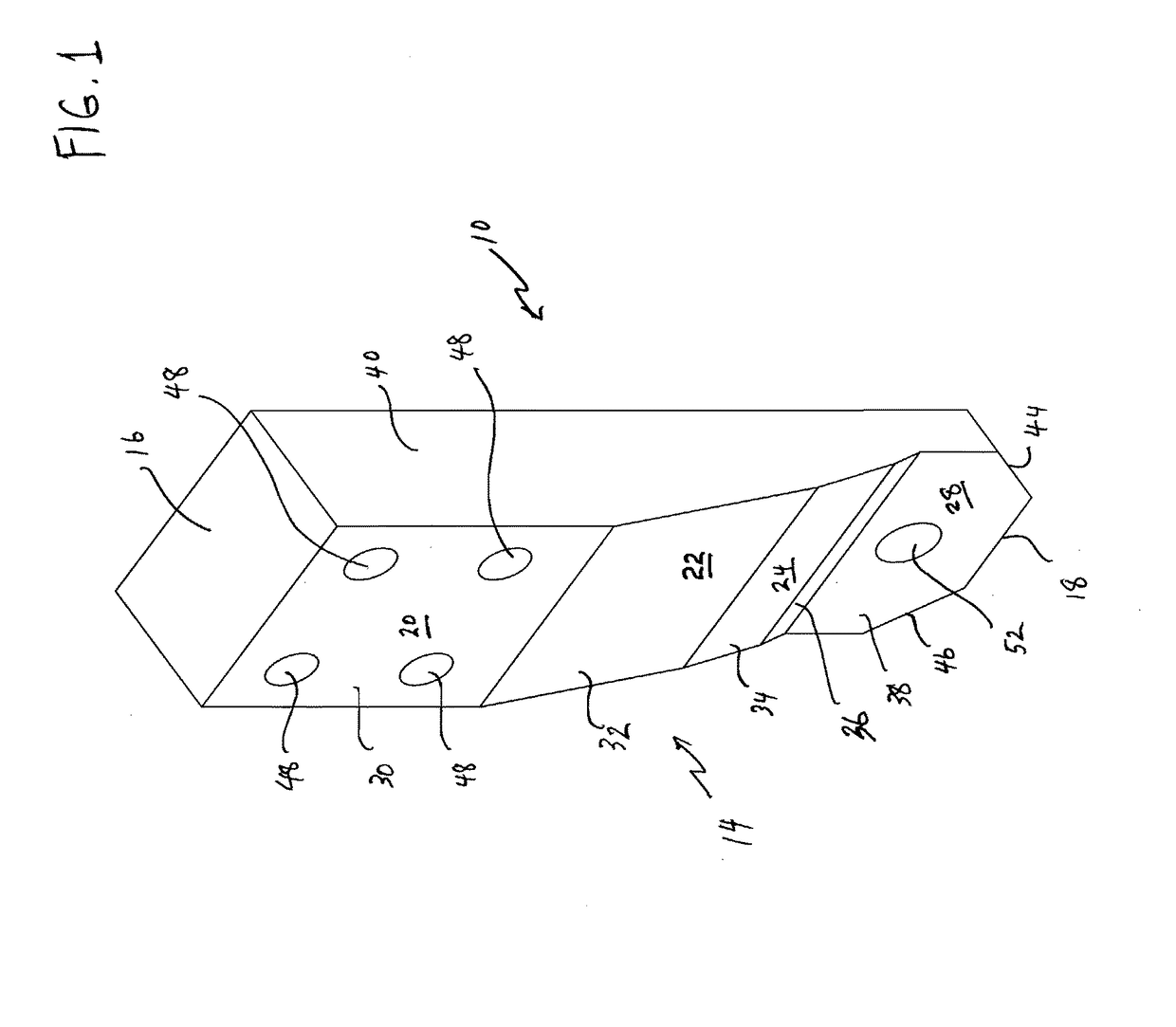
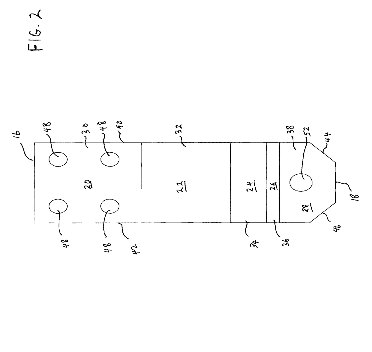
[0153]Referring to FIG. 1, there is shown one preferred embodiment of a high strength deflection plate 10 according to the present invention. The deflection plate 10, as shown, generally in FIGS. 1, 2 and 3, is a 100,000 pound (referred to here as 100 kip) embodiment which has a generally rectangular configuration having a flat back surface 12 and a front...


PUM

PropertyMeasurementUnit
forceaaaaaaaaaa
forceaaaaaaaaaa
tensionaaaaaaaaaa

Abstract

A load can be applied to a beam and a property of the load can be calculated. In one example, a first shear gauge can be configured for positioning on a neutral axis of a beam on one side of a force that the beam is subjected to. Similarly, a second shear gauge can be configured for positioning on the neutral axis of the beam on an opposite side of the force to the first shear gauge. A calculator can be configured to identify a characteristic of the force through use of an output of the first shear gauge and through use of an output of the second shear gauge.

Description

CROSS-REFERENCE[0001]This application is a continuation application of, and claims priority to, U.S. patent application Ser. No. 13 / 545,565 that was filed on Jul. 10, 2012, the entirety of which is hereby incorporated by reference.GOVERNMENT INTEREST[0002]The invention described herein may be manufactured, used, imported, sold, and licensed by or for the Government of the United States of America without the payment to me of any royalty thereon.FIELD OF THE INVENTION[0003]The present invention relates generally to deflection plates to protect load cells from overloading and, more particularly, to a deflection plate for the M16 and M18 Mobile Dynamometers used by the U.S. Army. The present invention also relates to a method for employing strain gages to identify the magnitudes and locations of loads on slender beams using strain gage based methods with application to portable Army bridges.BACKGROUND OF THE INVENTION[0004]A mobile dynamometer is a vehicle that can measure the force ne...

Claims


Application Information

Patent Timeline
Patent Type & Authority Patents(United States)
IPC IPC(8): G01L1/04G01L5/04G01L1/22G01L25/00
CPCG01L1/22G01L1/04G01L25/00G01L1/2206G01L1/26G01L1/00
Inventor BEDNARZ, EDWARDZHU, WEIDONG
Owner UNITED STATES OF AMERICA THE AS REPRESENTED BY THE SEC OF THE ARMY
Why Eureka
Try Eureka