

Switching device for ratchet wrench
a technology of ratchet wrench and switch, which is applied in the direction of wrenches, manufacturing tools, screwdrivers, etc., can solve the problems of affecting the value in the market, the wrench is not suitable for aesthetic purposes, and the bolts make the wrench not meet the requirements of aesthetic purposes, etc., and achieves high torque
- Summary
- Abstract
- Description
- Claims
- Application Information
AI Technical Summary
Benefits of technology
Problems solved by technology
Method used
Image

Examples
Embodiment Construction
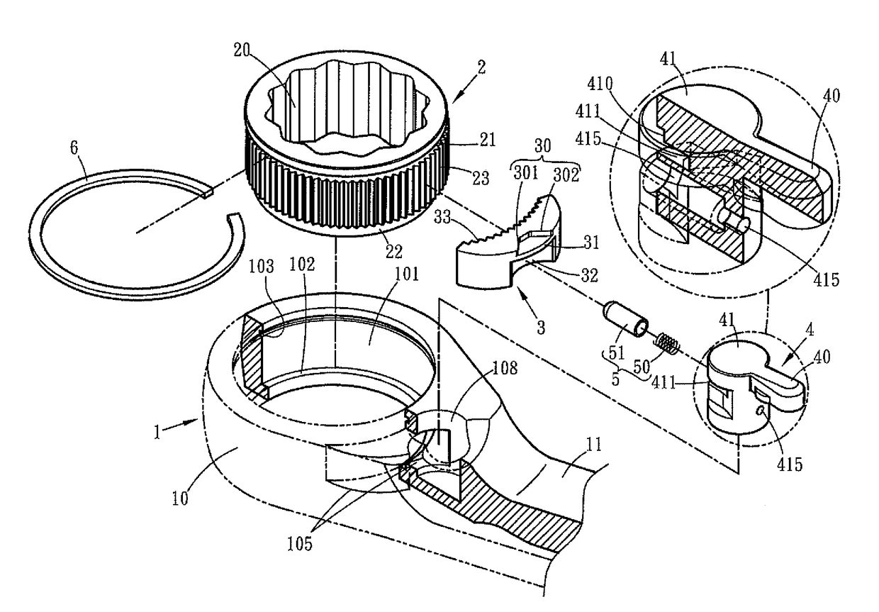
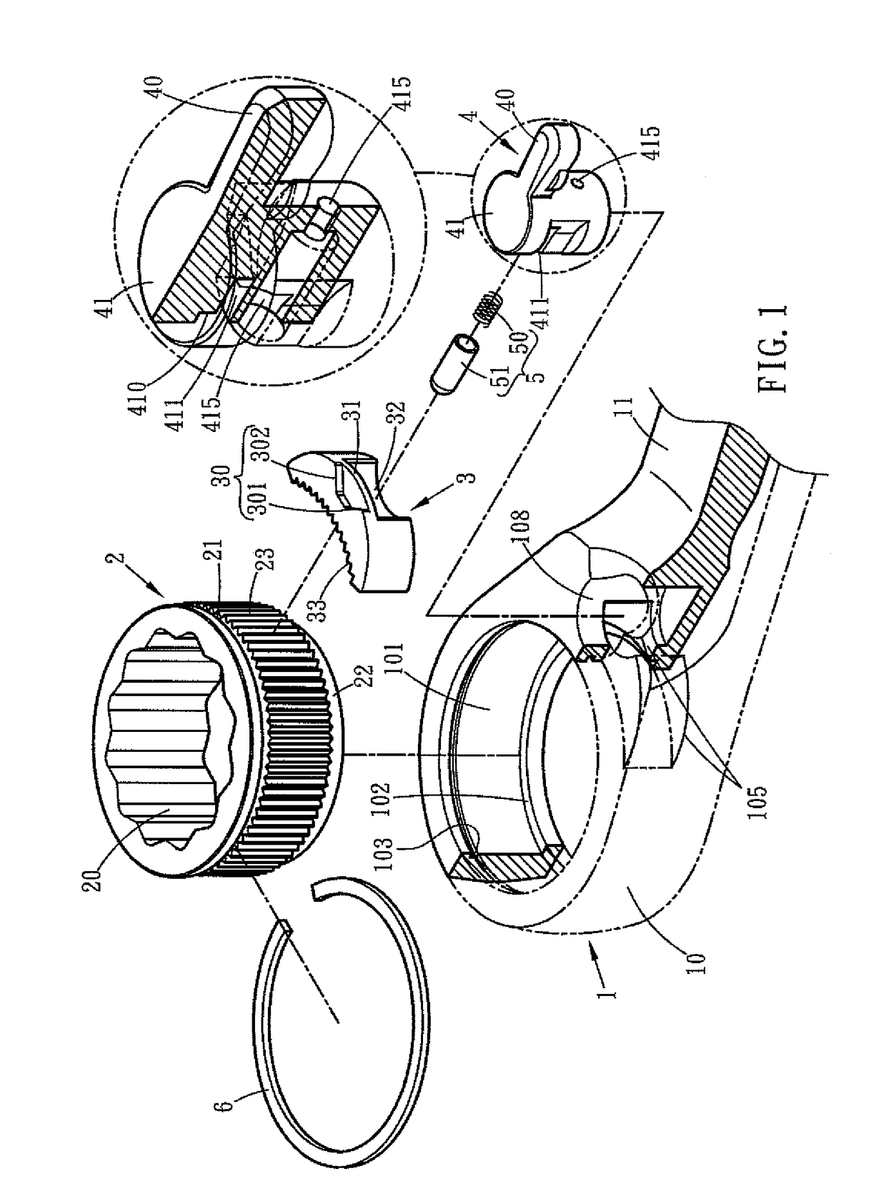
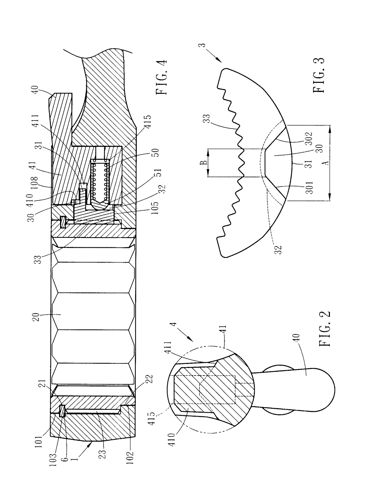
[0028]Referring to FIGS. 1 to 4, the ratchet wrench of the present invention comprises a body 1 having a head 10, and a handle 11 is connected to the head 10. The head 10 has a first room 101 defined therethrough. A second room 105 is defined in the inner periphery of the first room 101. A third room 108 is defined in the inner periphery of the second room 105 and has an opening which opens through a first side of the head 10. A support flange 102 extends inward from the inner periphery of the first room 101 and located at the lower portion of the head 10. A first groove 103 is defined in the inner periphery of the first room 101 and located at the top portion of the head 10. The second room 105 is located between and communicates with the first and third rooms 101, 108. The second room 105 is located beneath and covered by a portion of the head 10, and does not open to outside of the body 1 directly. The first groove 103 of the first room 101 and the opening of the third room 108 a...
PUM
 Abstract
Description
Claims
Application Information