Head worn display integrity monitor system and methods

a display integrity and monitor system technology, applied in the field of displays, can solve the problem that the integrity monitoring of head tracking functions is not currently monitored in the display system of head worn displays, and achieve the effect of monitoring the positional accuracy of the symbology

Active Publication Date: 2017-10-10
ROCKWELL COLLINS INC
View PDF89 Cites 54 Cited by
  • Summary
  • Abstract
  • Description
  • Claims
  • Application Information

AI Technical Summary

Problems solved by technology

However, head tracking functions are currently not monitored for integrity in head worn display systems.

Method used


Image

  • Head worn display integrity monitor system and methods
  • Head worn display integrity monitor system and methods
  • Head worn display integrity monitor system and methods

Examples


Embodiment Construction

[0016]Before describing in detail the particular improved system and method, it should be observed that the invention includes, but is not limited to, a novel structural combination of components and not in the particular detailed configurations thereof. Accordingly, the structure, software, optics, methods, functions, control and arrangement of components have been illustrated in the drawings by readily understandable block representations and schematic drawings in order not to obscure the disclosure with structural details which will be readily available to those of ordinary skill in the art having the benefit of the description herein. Further, the invention is not limited to the particular embodiments depicted in the exemplary diagrams, but should be construed in accordance with the language of the claims.

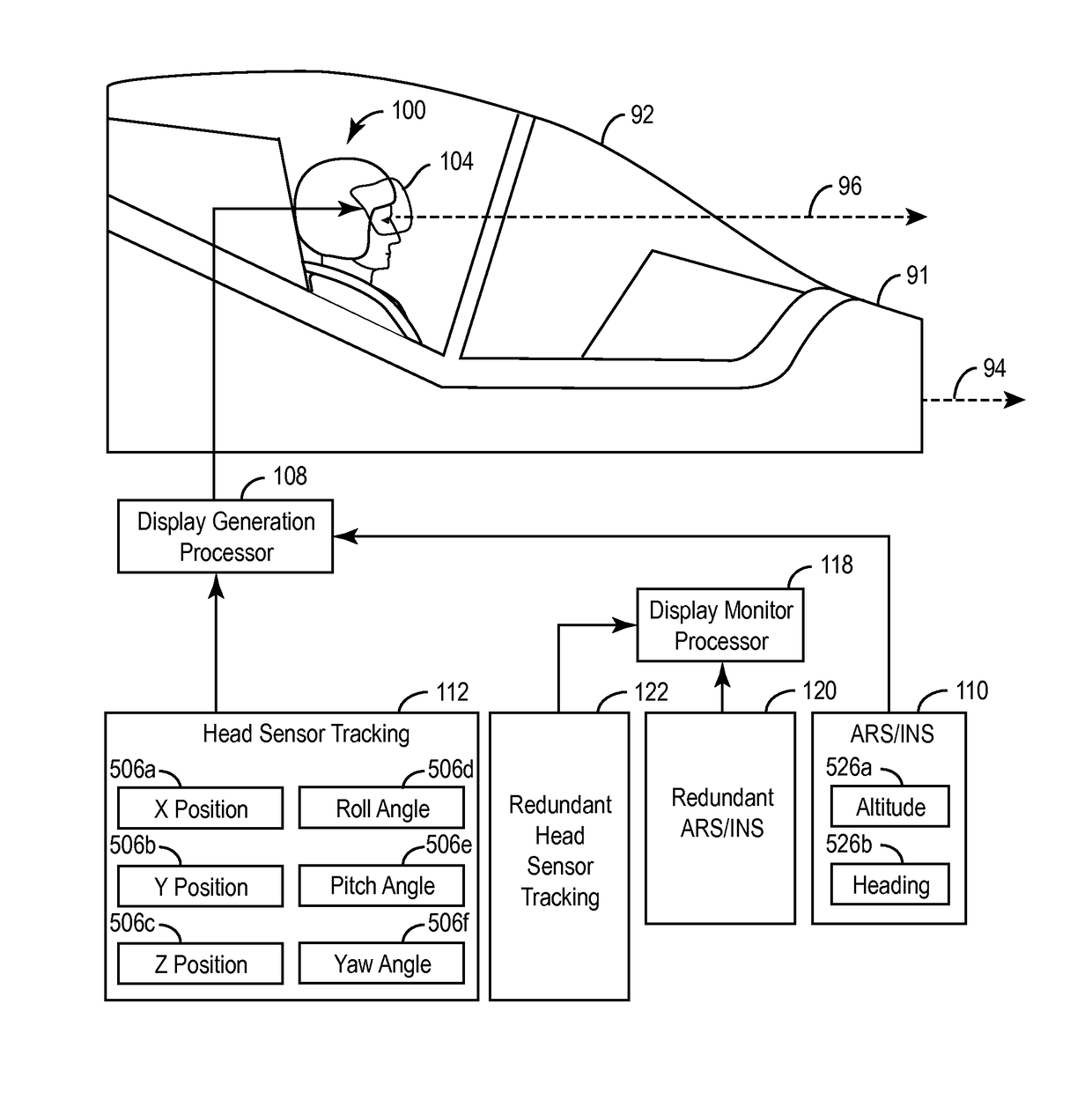
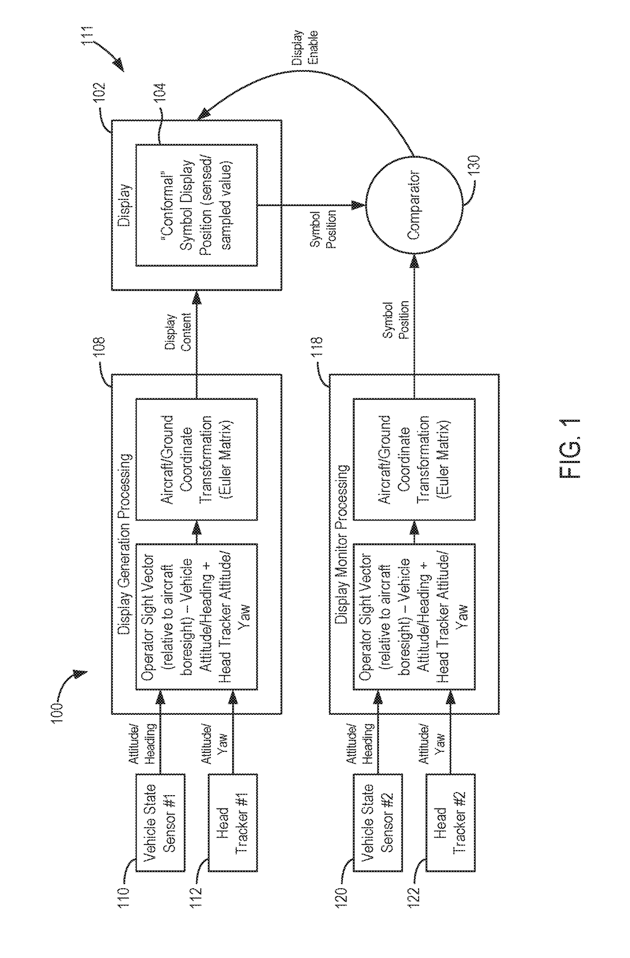
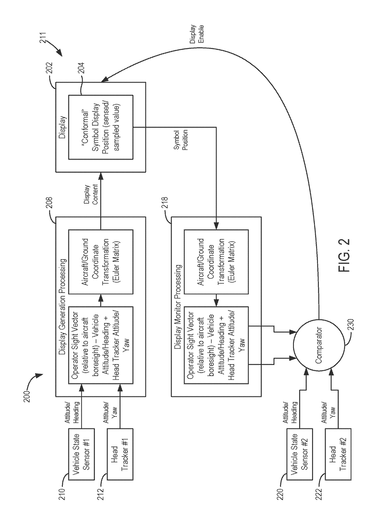
[0017]With reference to FIGS. 1, 4 and 5, a head worn display system 100 provides conformal display symbology 90 associated with an environment 11. System 100 can be embodied a...


PUM


Abstract

A head worn display system (e.g., helmet mounted (HMD) display system, and an eye wear mounted display system,) can include a combiner, a head position sensor and a computer. The computer provides symbology in response to first sensor input values associated with the head position. The symbology can be conformal with a real world scene. A monitoring system includes a redundant head position sensor for providing second sensor input values associated with head position. The computer monitors for positional accuracy of the symbology by comparing symbology calculated using the first and second input sensor values or by using an inverse function to compare sensor values.

Description

BACKGROUND OF THE INVENTION[0001]The present specification relates generally to the field of displays. More specifically, the specification relates to integrity monitoring for head worn displays.[0002]A head worn display (HWD) can be positioned in front of a user's eyes to provide operational capabilities similar to a fixed installation head up display (“HUD”). Head worn displays (e.g., helmet mounted displays, eyewear mounted displays, etc.) can provide information that is viewable in virtual space for the operation of equipment, such as aircraft, ships, boats, naval crafts, medical equipment, robotic equipment, remote vehicles, unmanned vehicle systems (“UVS”), training simulators, entertainment systems, military equipment, land vehicles, etc. The information can include navigation parameters, guidance parameters, equipment parameters, location information, video information, remote views, symbology, etc.[0003]Head worn displays can be used to overlay display symbology (e.g., one ...

Claims


Application Information

Patent Timeline
Patent Type & Authority Patents(United States)
IPC IPC(8): G09G5/377G02B27/01G06F3/01G02B27/00G06F3/0346G06F11/16
CPCG06F3/012G02B27/017G02B27/01G02B27/0093G02B2027/0198G06F11/1637G06F3/0346G02B2027/0187G02B2027/0167G06F11/1487G06F11/1641
Inventor ZIMMERMAN, KENNETH A.TIANA, CARLO L.BARBER, SARAH
Owner ROCKWELL COLLINS INC
Why Eureka
Try Eureka