Rolling type vehicle

a technology of rolling type and rolling body, which is applied in the direction of cycle equipment, transportation and packaging, cycle, etc., can solve the problems of inability to regulate the turning angle of the front wheels the limit of the turning angle of the front wheels cannot be varied according to the swinging angle, so as to reduce the turning angle, simple configuration, and avoid interference between the front wheels and the vehicle body

Inactive Publication Date: 2017-10-24
HONDA MOTOR CO LTD
View PDF4 Cites 2 Cited by
  • Summary
  • Abstract
  • Description
  • Claims
  • Application Information

AI Technical Summary

Benefits of technology

[0010]According to an embodiment of the present invention, the regulating means (60) is so configured as to reduce the turning angle when the swinging angle about the swing shaft (25a, 25b) exceeds a predetermined angle.
[0014]According to an embodiment of the present invention, the regulating means for regulating the turning angle of each front wheel is provided between the transversely outer end portion of at least one of the pair of left and right arm members and the knuckle member supported by the transversely outer end portion. This ensures that in the rolling type vehicle, the limit of the turning angle of the front wheel can be varied according to the swinging angle. Therefore, the turning angle of the front wheels can be regulated according to the roll angle (bank angle).
[0015]According to an embodiment of the present invention, the rolling type vehicle further includes the pair of left and right outer link members which are supported by the transversely outer end portions of the pair of left and right arm members swingably respectively about the swing shafts and which support the knuckle members steerably respectively about the left and right kingpin shafts intersecting the left and right swing shafts. This configuration ensures that even in the case where the transversely outer end portions of the left and right arm members swing respectively about the swing axes at the time of rolling (at the time of banking), the turning angle of the front wheel is regulated. Consequently, the turning angle of the front wheels can be regulated according to the roll angle (bank angle).
[0016]According to an embodiment of the present invention, the regulating means is formed so as to reduce the turning angle when the swinging angle about the swing shaft exceeds a predetermined angle. As a result of this, interference between the front wheels and the vehicle body can be avoided while securing a roll angle (bank angle).
[0017]According to an embodiment of the present invention, the regulating means includes the cam adapted to regulate the turning angle in conjunction with a variation in the swinging angle. With this configuration, the regulation of the turning angle of the front wheels according to the roll angle (bank angle) can be easily performed using a simple configuration. In addition, the operation of the regulating means at the time of rolling (banking) can be performed smoothly.
[0019]According to an embodiment of the present invention, the regulating means includes the cam disposed to overlap with the insertion portion as viewed from the direction along the swing shaft, and the roller capable of rolling along the outer circumference of the cam. With this configuration, friction during contact between the cam and the roller, namely, during the operation of the regulating means, can be reduced. Consequently, the operation of the regulating means at the time of rolling (at the time of banking) can be performed smoothly.

Problems solved by technology

However, when the turning angle regulating structure as above is applied as it is to a rolling type vehicle which has a pair of left and right front wheels and in which a vehicle body is capable of lateral swinging, or rolling, the limit of the turning angle of the front wheels cannot be varied according to the swinging angle.
For this reason, there has been a problem wherein the turning angle of the front wheels cannot be regulated according to the roll angle (bank angle).

Method used


Image

  • Rolling type vehicle
  • Rolling type vehicle
  • Rolling type vehicle

Examples


Embodiment Construction

[0039]An embodiment of the present invention will be described below, referring to the drawings. It is to be noted that the directions such as forward, rearward, leftward and rightward directions in the following description are the same as those directions with reference to a vehicle described hereinbelow, unless otherwise specified. In addition, at appropriate locations in the drawings used in the following description, there are shown an arrow FR indicative of the front side of the vehicle, an arrow LH indicative of the left-hand side of the vehicle, and an arrow UP indicative of the upper side of the vehicle. In addition, line CL in the drawings is a longitudinally extending vehicle body center line.

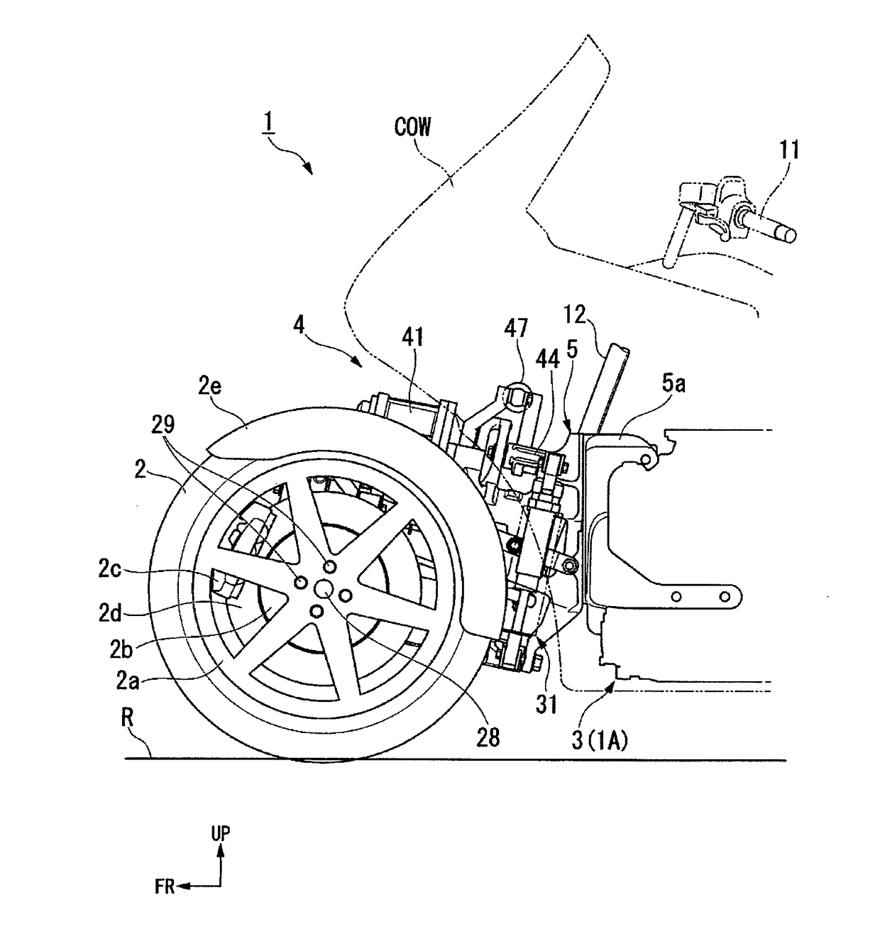
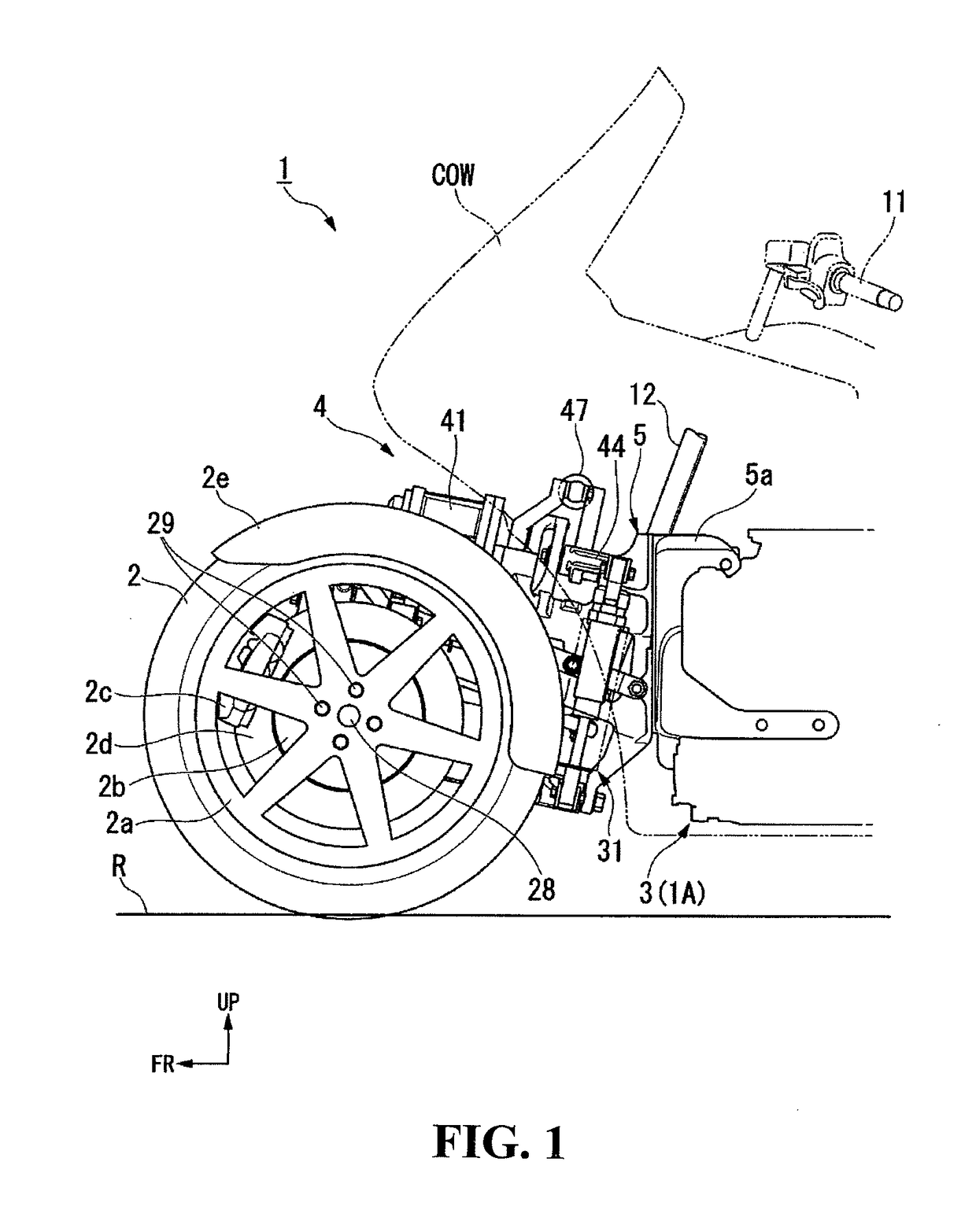
[0040]FIG. 1 shows a vehicle body front portion of a saddle type vehicle 1 in the present embodiment. The saddle type vehicle 1 is a two-front-wheeled three-wheel rolling type vehicle which includes a pair of left and right front wheels (steered wheels) 2 in left-right symmetry at ve...


PUM


Abstract

A rolling type vehicle includes a pair of left and right front wheels and has a vehicle body capable of rolling. The rolling type vehicle includes a pair of left and right arm members supported in a swingable manner by the vehicle body on inner sides in the transverse direction for supporting the left and right front wheels in a steerable manner on outer sides in the transverse direction. A pair of left and right knuckle members are supported by transversely outer end portions of the left and right arm members in a swingable manner and which are steered together with the left and right front wheels, respectively. A regulating member for regulating the turning angle of each front wheel is provided between the transversely outer end portion of at least one of the left and right arm members and the knuckle member supported by the transversely outer end portion.

Description

CROSS-REFERENCE TO RELATED APPLICATIONS[0001]The present application claims priority under 35 USC 119 to Japanese Patent Application No. 2015-024460 filed Feb. 10, 2015 the entire contents of which are hereby incorporated by reference.BACKGROUND OF THE INVENTION[0002]1. Field of the Invention[0003]The present invention relates to a rolling type vehicle.[0004]2. Description of Background Art[0005]A steering apparatus for a vehicle is known. See, for example, JP 2010-188914 A. This steering apparatus includes a leading arm by which a knuckle of a front wheel is supported steerably about a kingpin shaft, and a stopper is provided between the leading arm and the knuckle for regulating the turning angle of the knuckle with respect to the leading arm. In JP 2010-188914 A, the stopper provided on the knuckle makes contact with the stopper provided on the leading arm, whereby a limit of swinging of the knuckle with respect to the leading arm, or a limit of the turning angle in left-right di...

Claims


Application Information

Patent Timeline
Patent Type & Authority Patents(United States)
IPC IPC(8): B62D7/18B62K5/05B62K5/027B62K5/08B60G21/05B60G21/00B62K5/10B62D9/02B60G3/20B60G7/04B62K5/00B62K25/04
CPCB62D7/18B60G7/04B60G21/007B60G21/05B62D9/02B62K5/027B62K5/05B62K5/08B62K5/10B60G3/20B62K2025/044B60G2200/144B60G2200/184B60G2200/44B60G2202/42B60G2202/442B60G2204/42B60G2204/422B60G2204/4222B60G2204/45B60G2206/50B60G2300/122B60G2300/45B60G2800/24B62K2005/001
Inventor MORI, YOTAROYASUI, HISAKAZU
Owner HONDA MOTOR CO LTD
Why Eureka
Try Eureka