
Lock structure suitable for various lock cores

a technology of lock core and lock core, which is applied in the direction of latching locks, building locks, keyhole guards, etc., can solve the problems of failure of locking and unlocking, economic burden for the general consumer, and inability to replace the lock core, so as to reduce the economic burden of the user and improve the use of the lock core

Active Publication Date: 2017-10-31
CHEN TE YU
View PDF11 Cites 4 Cited by
  • Summary
  • Abstract
  • Description
  • Claims
  • Application Information

AI Technical Summary

Benefits of technology

The present invention offers a lock structure that can be used with different lock cores. This means that if the lock core gets damaged, it can be replaced with a lock core of a different type without having to replace the entire lock. This enhances the utilization of the lock and reduces the economic burden on the user.

Problems solved by technology

Since the lock core is repeatedly and frequently rotated back and forth, severe wear and even damage may occur after long-term use, leading to failure of locking and unlocking.
A conventional lock is designed and structured in such a way that replacement of the lock core is generally not possible and when the lock core is damaged, it is necessary to replace the entire lock, not just the lock core.
This would be an economic burden for the general consumers.

Method used


Image

  • Lock structure suitable for various lock cores
  • Lock structure suitable for various lock cores
  • Lock structure suitable for various lock cores

Examples


Embodiment Construction

[0019]The following descriptions are exemplary embodiments only, and are not intended to limit the scope, applicability or configuration of the invention in any way. Rather, the following description provides a convenient illustration for implementing exemplary embodiments of the invention. Various changes to the described embodiments may be made in the function and arrangement of the elements described without departing from the scope of the invention as set forth in the appended claims.

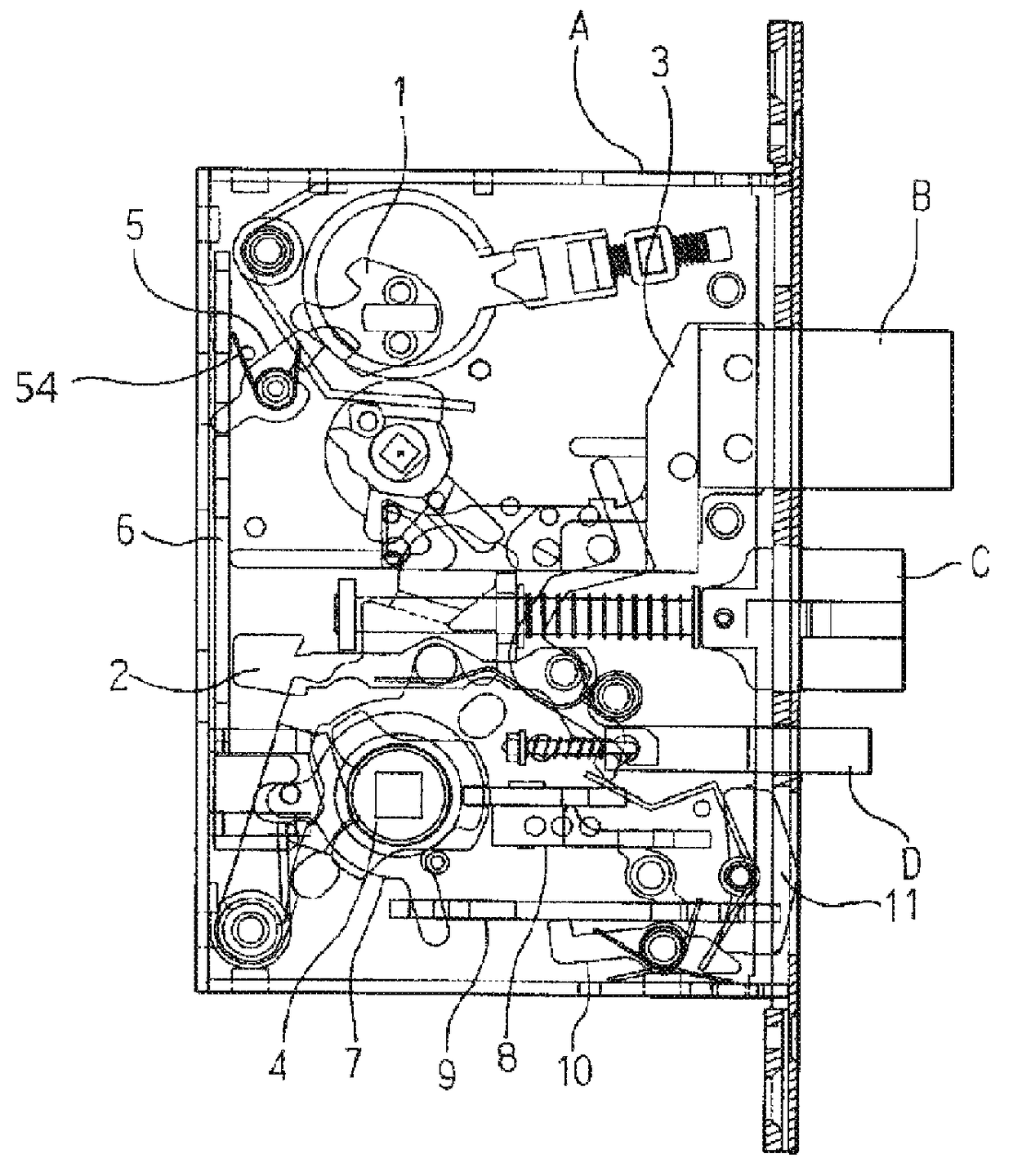
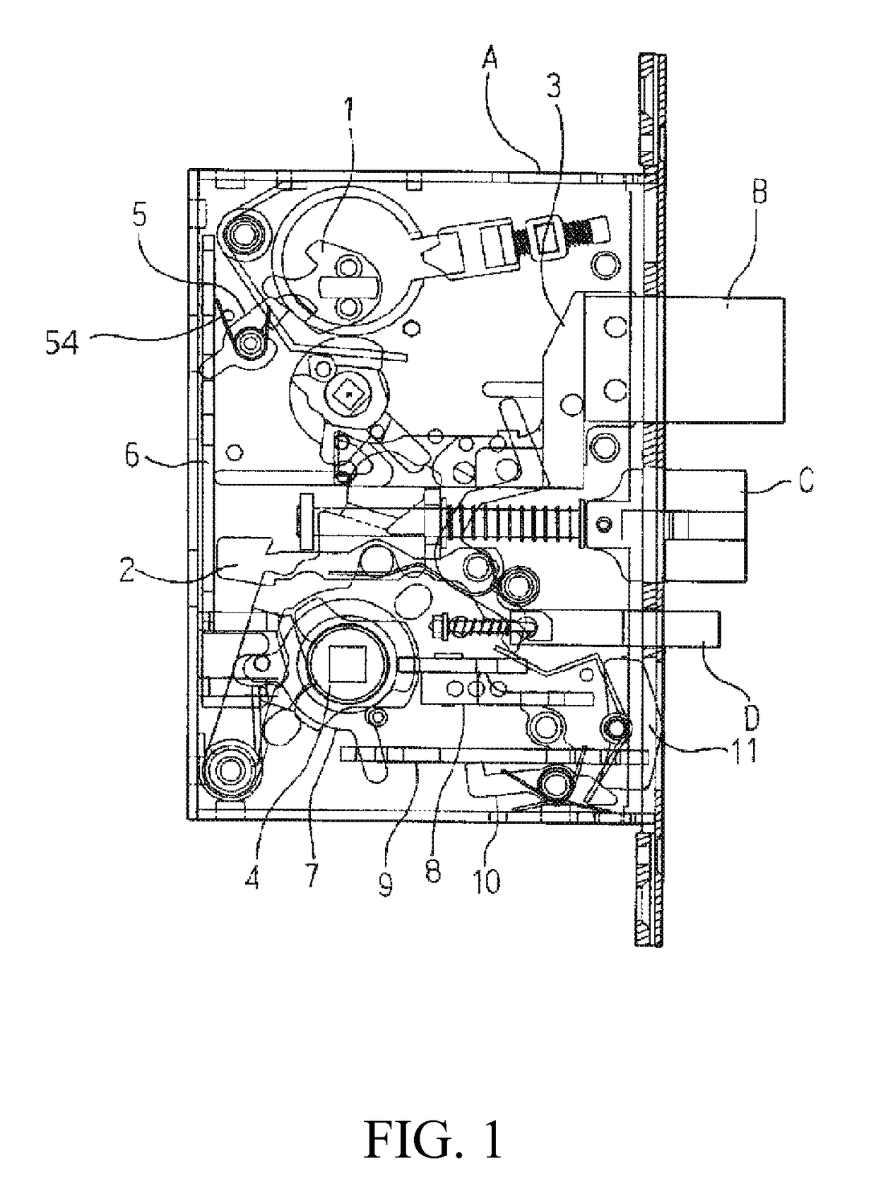
[0020]Referring to FIG. 1, a schematic view is given to illustrate a structure according to the present invention. As shown in the drawing, the present invention comprises, in lock device A, a rectangular bolt B, a triangular bolt C, and a latch D, and a lock core axle 1, an oscillation bar 2, a push bar 3, and a handle axle 4 that is rotatably mounted and coupled to a handle. An engagement member 5 is arranged at one side of the lock core axle 1 in such a way that the engagement member 5 is coupled...


PUM


Abstract

A lock structure suitable for various lock cores includes an engagement arranged at one side of a lock core axle of a lock device. The engagement member includes a rod section such that the engagement member is coupled to a link bar. A handle axle includes an arrestor member, such that the arrestor member is coupled to a stop plate and a push bar. A retention member is arranged under the push bar. When the lock core axle is rotated by means of a key, the engagement member and the link bar are driven to achieve locking, or a handle is operated to achieve unlocking. When the lock core is damaged, the damaged lock core is replaceable with one of various types of lock core without the need to replace the entire lock thereby improving the utilization of the lock.

Description

(a) TECHNICAL FIELD OF THE INVENTION[0001]The present invention relates generally to a lock structure that is suitable for various lock cores, and more particularly to a lock structure that allows for replacement of a damaged lock core with various types of lock core without the need to change the entire lock so that the utilization of the lock can be improved.(b) DESCRIPTION OF THE PRIOR ART[0002]A regular lock, when locked from the indoor side, is often operated by means of a rotary axle for locking, and when locked from the outdoor side, is operated with a key to rotate a lock core axle for locking and unlocking. Since the lock core is repeatedly and frequently rotated back and forth, severe wear and even damage may occur after long-term use, leading to failure of locking and unlocking. A conventional lock is designed and structured in such a way that replacement of the lock core is generally not possible and when the lock core is damaged, it is necessary to replace the entire lo...

Claims


Application Information

Patent Timeline
Patent Type & Authority Patents(United States)
IPC IPC(8): E05B63/08E05B9/08E05B15/00E05B59/00E05B13/00
CPCE05B63/08E05B9/084E05B59/00E05B15/00Y10T70/7661E05B13/004
Inventor CHEN, TE-YU
Owner CHEN TE YU
Learn More