Optical sheet holding structure and display apparatus

a technology of optical sheets and holding structures, applied in mechanical devices, lighting and heating devices, instruments, etc., can solve the problems of uneven luminance and decrease of luminance of display apparatus, and achieve the effects of improving workability, stably locking, and easy pushed

Active Publication Date: 2017-11-07
SAKAI DISPLAY PROD
View PDF13 Cites 0 Cited by
  • Summary
  • Abstract
  • Description
  • Claims
  • Application Information

AI Technical Summary

Benefits of technology

[0009]In particular, the hole of the optical sheet is larger than the positioning pin. Briefly, there is a gap between the hole and the positioning pin. By having the gap, it is possible to cope with a positional shift of the hole due to the thermal expansion of the optical sheet, and easily perform an assembling process.
[0033]According to the present invention, the positional shift on the plane of the optical sheet in the display apparatus, and the fluctuation in the thickness direction may be restrained. Thereby, it is possible to prevent an occurrence of wrinkling, bending, and breakage of the optical sheet in the display apparatus, and prevent problems such as uneven luminance, or luminance degradation.

Problems solved by technology

Thereby, problems such as luminance unevenness, or a decrease in luminance of display apparatus occurs.

Method used


Image

  • Optical sheet holding structure and display apparatus
  • Optical sheet holding structure and display apparatus
  • Optical sheet holding structure and display apparatus

Examples


embodiment 1

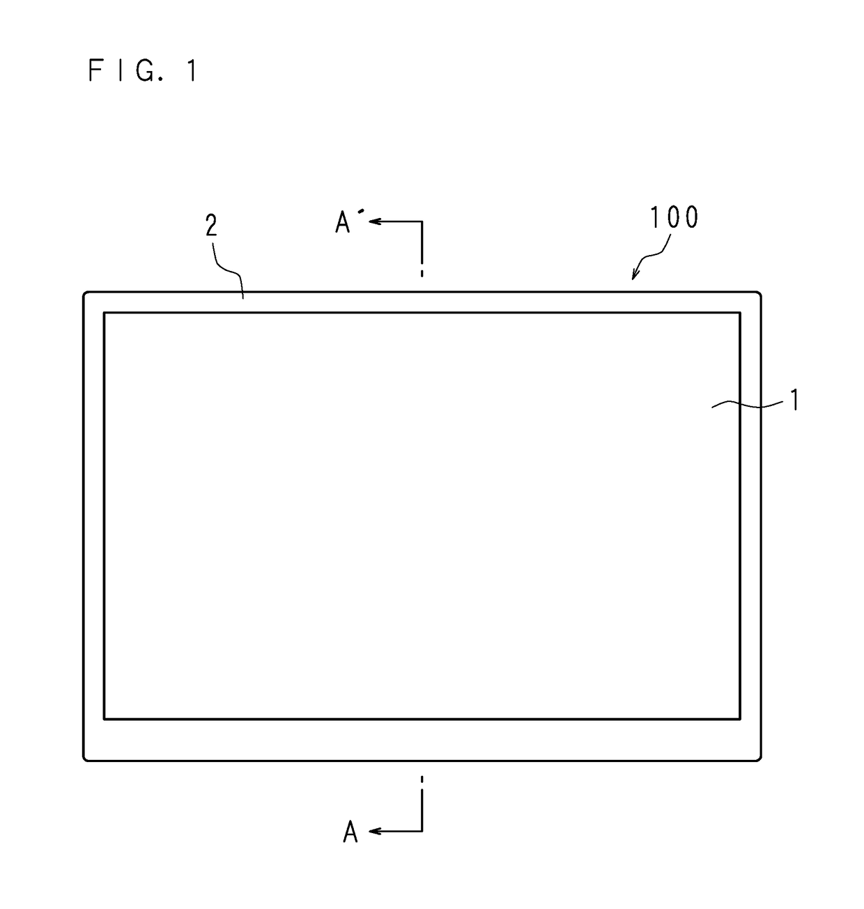
[0052]FIG. 1 is a front view illustrating an appearance of a display apparatus 100 according to Embodiment 1. The display apparatus 100 is formed by positioning and housing a liquid crystal panel 1 and other parts by a plurality of other chassis including a first chassis 2.

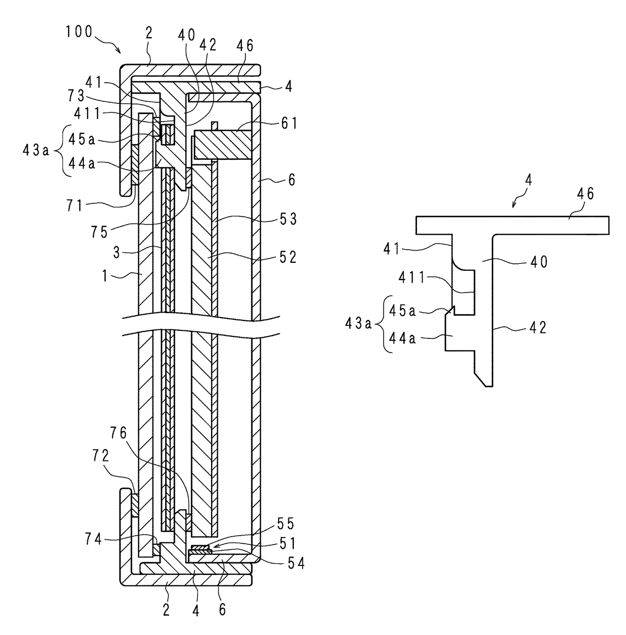
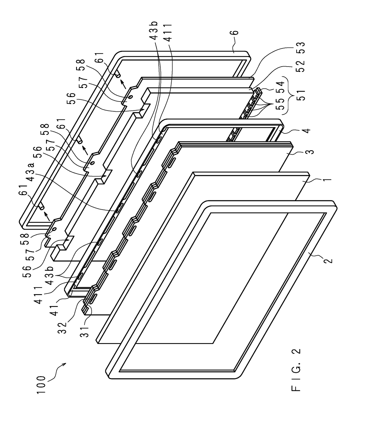
[0053]FIG. 2 is an exploded perspective view schematically illustrating main components included in the display apparatus 100 according to Embodiment 1, and FIG. 3 is a longitudinal-sectional view taken on line A-A′ of FIG. 1.

[0054]The display apparatus 100 includes the liquid crystal panel 1, the first chassis 2, an optical sheet 3, a second chassis 4, a light guide plate 52, a light source 51, a reflection sheet 53, and a third chassis 6.

[0055]The first chassis 2 is a rectangular frame body. The first chassis 2 includes a rectangular and cylindrical-shaped side plate, and a frame part of an annular plate protruding inward from one end portion of the side plate, and has an L-shaped cross section.

[0056]The liquid ...

embodiment 2

[0084]The shape of the engaging part is not limited to the shape disclosed in Embodiment 1. FIG. 8 is a front view schematically illustrating an edge part of a second chassis 4 according to Embodiment 2, and FIG. 9 is a longitudinal-sectional view taken on line C-C′ of FIG. 8. A configuration of the second chassis 4 according to Embodiment 2 is the same as the configuration according to Embodiment 1 other than the shape of a holding surface 41 which will be described below. Therefore, the configuration equivalent thereto will be denoted by the same reference numerals, and will not be described in detail.

[0085]FIG. 8 shows a periphery of a center engaging part 43a in an enlarged form, among the edge parts provided with engaging parts 43a and 43b of the second chassis 4 according to Embodiment 2. In Embodiment 2, an escape part (concave) 47a recessed in the thickness direction is provided at a portion of the reception part 411 facing an engaging piece 45a, that is, at a location where...

embodiment 3

[0089]FIG. 10 is a front view schematically illustrating an edge part of a second chassis 4 according to Embodiment 3. Since the longitudinal section of an engaging part 43c according to Embodiment 3 passing through an engaging piece 45c is the same as the longitudinal section of the engaging part 43a according to Embodiment 1, the cross-sectional view thereof will not be illustrated. A configuration of the second chassis 4 according to Embodiment 3 is the same as the configuration according to Embodiment 1 other than the shape of the engaging part 43c. Therefore, the configuration equivalent thereto will be denoted by the same reference numerals, and will not be described in detail.

[0090]The engaging part 43c of Embodiment 3 has a plurality of engaging pieces 45c. Specifically, in the engaging part 43c according to Embodiment 3, two engaging pieces 45c are formed by respectively extending a front tip of a base 44c from both ends thereof to the outside of the frame of the second cha...


PUM

PropertyMeasurementUnit
structureaaaaaaaaaa
lengthaaaaaaaaaa
thicknessaaaaaaaaaa

Abstract

Provided are an optical sheet holding structure capable of preventing an optical sheet from wrinkling and bending in a display apparatus, and from breakage during a vibration test, thereby preventing occurrence of problems such as uneven luminance, luminance degradation and the like, and a display apparatus including the optical sheet holding structure.A chassis for holding an optical sheet includes an engaging part for engaging the optical sheet. The engaging part includes a base provided to stand on a surface of a holding plate for the optical sheet orthogonally to the holding plate and in the thickness direction of the holding plate, and an engaging portion extending substantially parallel to a holding surface from the front edge of the base toward the outside of the frame of the chassis. A distance between the holding surface of the holding plate for the optical sheet and the surface of the engaging piece facing the holding surface is substantially equal to the thickness of the optical sheet. The cross-section of the base of a central engaging part is formed into a shape substantially identical to the shape of an engagement hole provided in the optical sheet.

Description

[0001]This application is the national phase under 35 U.S.C. §371 of PCT International Application No. PCT / JP2013 / 081630 which has an International filing date of Nov. 25, 2013 and designated the United States of America.BACKGROUND OF THE INVENTION[0002]1. Field of the Invention[0003]The present invention relates to a display apparatus which displays an image using a liquid crystal panel. Particularly, the present invention relates to an optical sheet holding structure and a display apparatus which has the optical sheet holding structure capable of preventing an occurrence of problems such as uneven luminance, or luminance degradation and the like, due to wrinkles, bending, or the like of the optical sheet used in the display apparatus, while achieving slimmed border of the display apparatus.[0004]2. Description of Related Art[0005]A display apparatus using a liquid crystal panel is provided with an optical sheet for diffusing or collecting light emitted from a light source. The opt...

Claims


Application Information

Patent Timeline
Patent Type & Authority Patents(United States)
IPC IPC(8): F21V8/00G02F1/1335G02F1/1333F21V17/00
CPCG02B6/0088F21V17/00G02F1/133308G02F1/133606G02F2201/46G02F2001/133317G02F2001/133607G02F2201/54G02F1/133317G02F1/133607
Inventor KAWABATA, RYOTAMATSUMOTO, KOUJI
Owner SAKAI DISPLAY PROD
Why Eureka
Try Eureka