Touch panel and production method thereof
a technology of touch panel and capacitance change, applied in the field of touch panel, can solve the problems of difficult to sensitively detect the size of the screen of recent electronic devices has increased, etc., and achieve the effect of sensitively detecting a change in capacitan
- Summary
- Abstract
- Description
- Claims
- Application Information
AI Technical Summary
Benefits of technology
Problems solved by technology
Method used
Image
Examples
embodiment 1
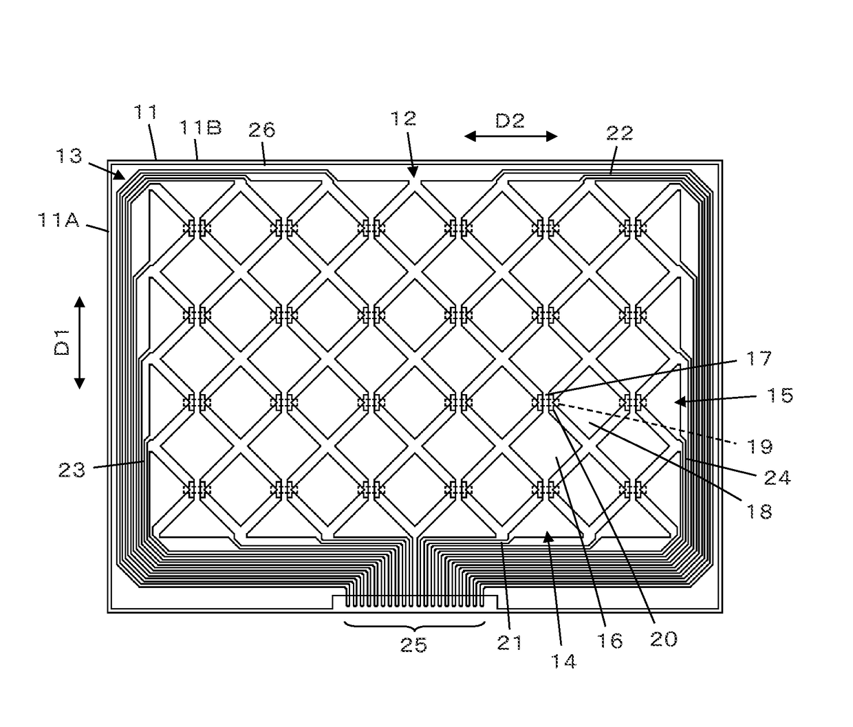
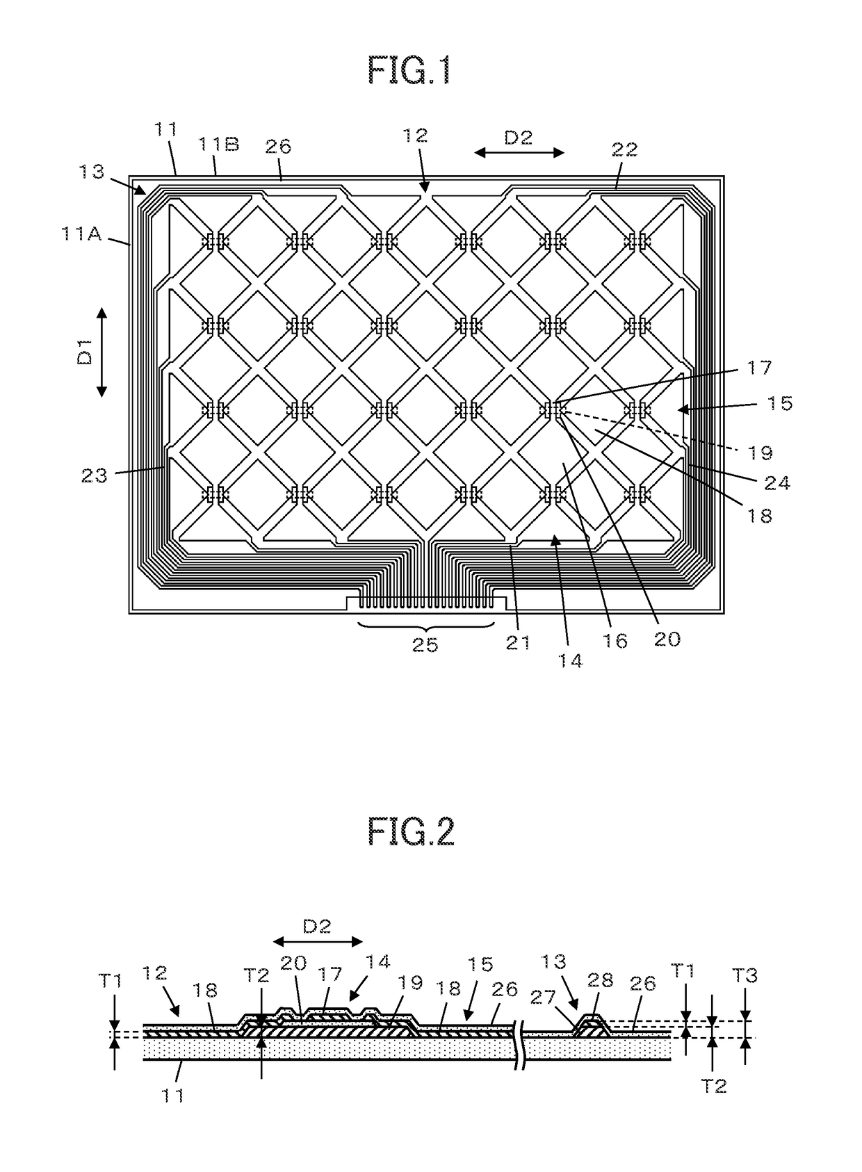
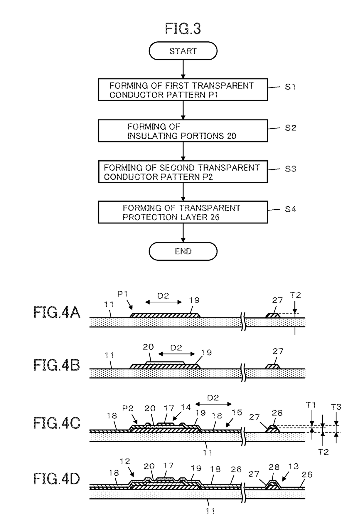
[0041]FIG. 1 illustrates a configuration of a touch panel according to Embodiment 1 of the present invention. The touch panel includes a transparent substrate 11 having a rectangular shape, a sensor electrode portion 12 formed on a surface of the transparent substrate 11, and a lead-out wiring portion 13 formed around the sensor electrode portion 12 on the surface of the transparent substrate 11.
[0042]The sensor electrode portion 12 includes a plurality of first sensor electrode arrays 14, extending along a first direction D1 and arranged parallel to one another along a second direction D2, and a plurality of second sensor electrode arrays 15, extending along the second direction D2 and arranged parallel to one another along the first direction D1, the first direction D1 being in parallel with a short side portion 11A of the rectangular transparent substrate 11, whereas the second direction D2 being in parallel with a long side portion 11B of the transparent substrate 11, i.e., orth...
embodiment 2
[0075]A touch panel according to Embodiment 2 is illustrated in FIG. 8. In the touch panel, a sensor electrode portion 12 and a lead-out wiring portion 33 are formed on a transparent substrate 31. Although not shown, a transparent protection layer is formed over the sensor electrode portion 12 and the lead-out wiring portion 33, similarly to the touch panel according to Embodiment 1.
[0076]The sensor electrode portion 12 is same as the sensor electrode portion 12 used in the touch panel according to Embodiment 1.
[0077]The lead-out wiring portion 33 includes a first wiring portion 21 connected to one end of each of first sensor electrode arrays 14 extending along a first direction D1 and a second wiring portion 23 connected to one end of each of second sensor electrode arrays 15 extending along a second direction D2, and the first wiring portion 21 and the second wiring portion 23 run to reach a terminal region 25.
[0078]A plurality of first island-shaped electrode portions 16 of each ...
embodiment 3
[0081]In the touch panel according to Embodiment 1, a single sensor electrode portion 12 and a single lead-out wiring portion 13 are formed on the transparent substrate 11. However, two sensor electrode portions 12 and two lead-out wiring portions 13 corresponding to the two sensor electrode portions 12 can be formed on a single transparent substrate 41 as illustrated in FIG. 9.
[0082]While a part of the lead-out wiring portion 13 is arranged between the two sensor electrode portions 12, as the lead-out wiring portion 13 is formed of the third transparent conductor layer, the part between the two sensor electrode portions 12 does not need to be masked, and the entire area of the transparent substrate 41 can be a display region of a display device to be used in combination with a touch panel.
[0083]On the other hand, in a conventional touch panel using a metal wiring, the metal wiring could not be arranged between two sensor electrode portions 12 since any opaque part should not be for...
PUM
| Property | Measurement | Unit |
|---|---|---|
| transparent | aaaaa | aaaaa |
| thickness | aaaaa | aaaaa |
| transmittance | aaaaa | aaaaa |
Abstract
Description
Claims
Application Information
 - R&D
- Intellectual Property
- Life Sciences
- Materials
- Tech Scout
- Unparalleled Data Quality
- Higher Quality Content
- 60% Fewer Hallucinations
Browse by: Latest US Patents, China's latest patents, Technical Efficacy Thesaurus, Application Domain, Technology Topic, Popular Technical Reports.
© 2025 PatSnap. All rights reserved.Legal|Privacy policy|Modern Slavery Act Transparency Statement|Sitemap|About US| Contact US: help@patsnap.com


