Integrated steering device

a steering device and integrated technology, applied in the field of multi-directional medical instruments, can solve the problems of difficult to see parts of the human anatomy, not always oriented, and difficult to navigate channels in the human body,

Active Publication Date: 2017-11-21
G I VIEW LTD (IL)
View PDF39 Cites 2 Cited by
  • Summary
  • Abstract
  • Description
  • Claims
  • Application Information

AI Technical Summary

Benefits of technology

[0010]The present invention provides a novel steering device which may be incorporated or coupled to any endoscopic tool, having better navigation and tracking, a superior interface with the operator, improved access by reduced frictional forces upon the lumenal tissue, increased patient comfort, and greater clinical productivity and patient throughput than those that are currently available.
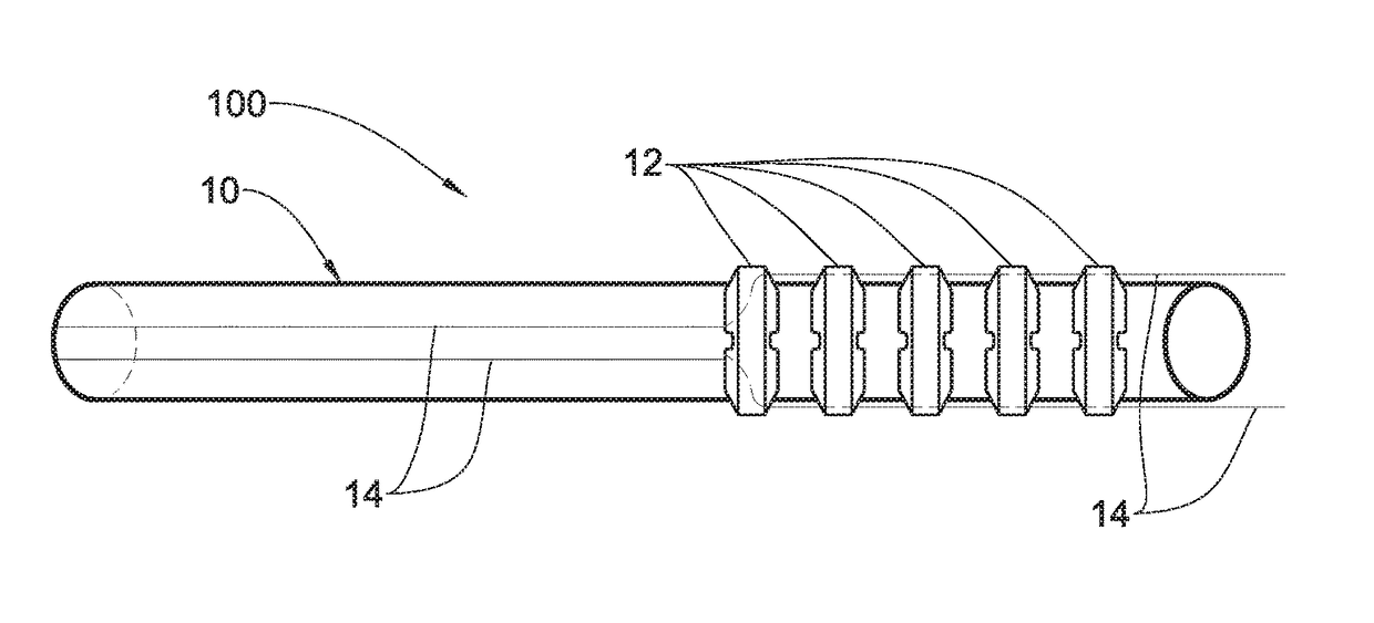
[0011]Therefore, according to one broad aspect of the present invention, there is provided a steering device for use in a body lumen of a patient, comprising: a flexible tube; a plurality of spaced-apart elements positioned along at least a portion of the tube; the plurality of spaced-apart elements and the tube forming a single integrated unit; and at least two steering wires having at least a portion passing through the spaced-apart elements and at least a portion passing within the tube. Using the novel configuration of the steering device in which the spaced-apart elements are integrated with a flexible tube and not mounted on another tube enables to provide a steering device with a higher flexibility and in which minimal deflection force has to be applied in order to bend the bending portion of the tube. In addition, this novel invention requires less moving parts, less complicated manufacturing techniques and allows easy and quick installation. It should be understood that conventional steering devices comprise an elongated main body having a scope therethrough.
[0012]U.S. Pat. No. 7,637,905 of Saadat describes a steerable tool with at least one steerable tool arm which extends from the distal end of the main body. In this disclosure, the steerable tool arm is a stand-alone unit which can be separated from the main body and is not integrated to the main body. This type of configuration has lower flexibility because the steering device comprises two separate stand-alone elements (e.g. the main body and the steerable arm) made of usually two different materials and constituting two different layers extending along the steering part of the device. Moreover, higher deflection force has to be applied in order to bend the bending portion of the tube, in order to bend the main body as well as the steerable arm creating a higher load. Furthermore, friction forces are created between the main body and the steerable arm layers. To overcome these disadvantages, the novel steering device of the present invention provides a single integrated unit comprising a tube with spaced-apart elements enabling the steering of the device. Moreover, the configuration of the novel steering device of the present invention eliminates stiff mechanical linkages between the adjacent links to ensure bending, and provides a soft tube that can be bent and twisted at any possible direction, thus allowing greater mobility that requires fewer elements.
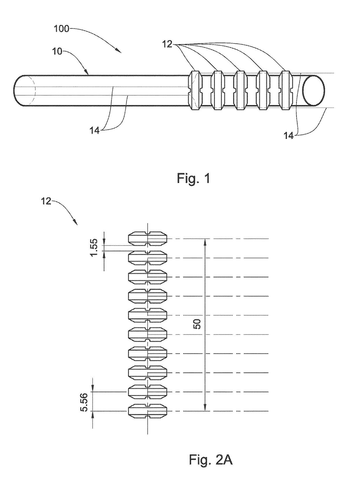
[0015]In some embodiments, the spaced-apart elements are separated by a constant distance between them. In this connection, it should be understood that the distance between the elements determines the properties of the tube, such as its flexibility and bending properties, as well as the shape of the bent tip / distal end of the tube. The distance between the spaced-apart elements is determined according to the specific material of the flexible tube. The distance between the spaced-apart elements is selected in such a way that prevents sharp bends of the tube that may lead to narrowing of the channels or the tube itself.
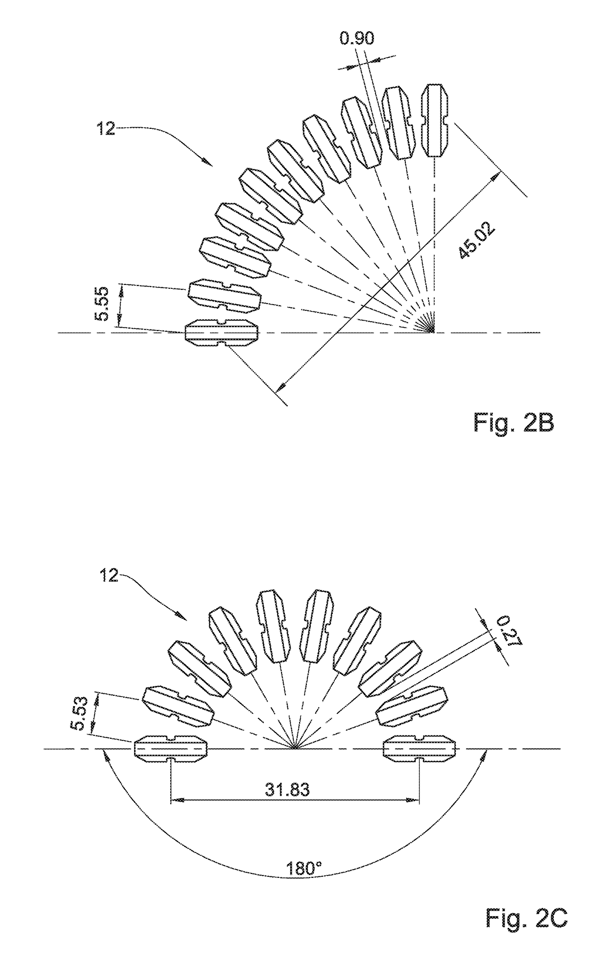
[0018]In some embodiments, at least one spaced-apart element has a cross-sectional geometrical shape defining a tapered section from both sides such that, while in a bent state when pulling on at least one steering wire, a U-shape of the tube is achieved. In this way, the creation of elbows, or folded portions, is prevented. The U-shape of the tube is determined by the distance between the spaced-apart elements and the angle of the tapered section.
[0024]As described above, the steering device of the present invention may also be an integral part of an endoscopic system comprising an image capturing device which is steered to any desired destination to enable to image a body lumen. The steering device is configured and operable to bend the flexible distal end of the endoscopic system such that a space is created between the body lumen and an image-capturing device to facilitate imaging of the body lumen.

Problems solved by technology

Navigating channels in the human body can be very challenging.
Some parts of the human anatomy can be difficult to see and are not always oriented in a convenient location relative to the position of the scope or surgical instrument.
Occasionally, the anatomy and the degrees of freedom of the instruments can impede or prevent successful navigation.
However, this type of procedure is generally difficult to perform, and / or painful for the patient due to stretching of the colon which occurs upon impact between the colonoscope and the wall of the colon as the colonoscope is advanced, especially during advancement of the colonoscope around the bends of the tortuous sigmoid colon.
By manipulating the control knobs, the examiner is usually able to steer the endoscope during insertion and direct it to a region of interest, in spite of the limitations of such traditional control systems, which are clumsy, non-intuitive, and friction-limited.
Common operator complaints about traditional endoscopes include their limited flexibility, limited column strength, and limited operator control of stiffness along the scope length.
Conventional endoscopes are generally built of sturdy materials, which decrease the flexibility of the scope and thus can decrease patient comfort.
Furthermore, conventional endoscopes are complex and fragile instruments that frequently need costly repair as a result of damage during use or during a disinfection procedure.
Still, many procedures using steerable instruments remain difficult.

Method used


Image

  • Integrated steering device
  • Integrated steering device
  • Integrated steering device

Examples


Embodiment Construction

[0037]Reference is made to FIG. 1 illustrating one possible configuration of the steering device of the present invention according to one embodiment of the present invention. The steering device is integrated with a flexible tube and is configured to direct and orient the distal end of the tube in any desired direction and at any desired angle. In particular, the invention relates to a novel steering device being configured and operable to direct and orient the tip of a tool within a body lumen to facilitate steering of the tool from outside of the patient's body. The steering device 100 for use in a body lumen of a patient, comprises a flexible tube 10, a plurality of spaced-apart elements 12 positioned along at least a portion of the tube 10, and at least two steering wires 14 having at least a portion passing through the spaced-apart elements 12 and at least a portion passing within the flexible tube 10. The spaced-apart elements 12 and the tube 10 form a single integrated unit....


PUM


Abstract

The present invention discloses a steering device for use in a body lumen of a patient. The steering device comprises a flexible tube; a plurality of spaced-apart elements positioned along at least a portion of the tube; wherein the plurality of spaced-apart elements and the tube form a single integrated unit; and at least two steering wires having at least a portion passing through the spaced-apart elements and at least a portion passing within the tube. According to another broad aspect of the present invention, there is provided a steering device for use in a body lumen of a patient, comprising: a flexible tube; at least two steering wires having at least a portion passing within the flexible tube; at least two spring-like sleeves; each spring-like sleeve at least partially enclosing a steering wire respectively; wherein the spring-like sleeve has a variable pitch along its length; such that the flexible tube comprises at least two portions having different bending properties.

Description

FIELD OF THE INVENTION[0001]The present invention relates generally to the field of multidirectional medical instruments, and more specifically, to steerable medical instruments.BACKGROUND OF THE INVENTION[0002]Endoscopes and imaging catheters are widely used in many medical procedures for viewing areas of bodily organs, cavities, passageways, etc. Generally, such imaging devices include an elongated sheath or similar structure wherein optical fibers are arranged both for transmitting illumination light to the distal end of the sheath to illuminate a viewing field, and for carrying an optical image back to a viewing port or camera. One or more lenses may be positioned on the distal end of the imaging device to focus the optical image received by, or the illumination cast by the instrument.[0003]In many applications, it is desirable that the distal portion of the imaging device be “steerable”, bendable or maneuverable from the proximal end of the device to facilitate guidance of the ...

Claims


Application Information

Patent Timeline
Patent Type & Authority Patents(United States)
IPC IPC(8): A61B1/00A61B1/018A61B1/015A61B1/012A61M25/01A61B1/005A61B1/06A61B1/31A61B10/04A61B17/00A61B1/04A61M25/00
CPCA61B1/0055A61B1/00114A61B1/015A61B1/018A61B1/0125A61B1/04A61B1/06A61B1/31A61B10/04A61B17/00234A61M25/0141A61M25/0147A61B1/0057A61M2025/0036A61B2017/0034A61B2017/00314A61B2017/00323A61M25/0032A61M25/0138
Inventor SIMCHONY, TALSINAY, AVRAHAMKRIVORUK, ILIA
Owner G I VIEW LTD (IL)
Why Eureka
Try Eureka