Supercharge Your Innovation With Domain-Expert AI Agents!

Tire air pressure monitoring system

a technology of air pressure monitoring and tire, which is applied in the direction of vehicle tyre testing, tire measurement, vehicle components, etc., can solve the problems of difficulty in prolonging the life of the tpms sensor battery, and achieve the effect of suppressing the power consumption of the tire air pressure transmission devi

Active Publication Date: 2017-11-21
NISSAN MOTOR CO LTD
View PDF12 Cites 1 Cited by
  • Summary
  • Abstract
  • Description
  • Claims
  • Application Information

AI Technical Summary

Benefits of technology

[0005]The objective of the present invention resides in providing a tire air pressure monitoring system which may suppress the power consumption of the tire air pressure transmission device.
[0007]Consequently, according to the present invention, the power consumption of the tire air pressure transmission device may be suppressed.

Problems solved by technology

Thus, there has been a problem of difficulty in extending a lifetime of a battery of the TPMS sensor (tire air pressure transmission device).

Method used


Image

  • Tire air pressure monitoring system
  • Tire air pressure monitoring system
  • Tire air pressure monitoring system

Examples


Embodiment Construction

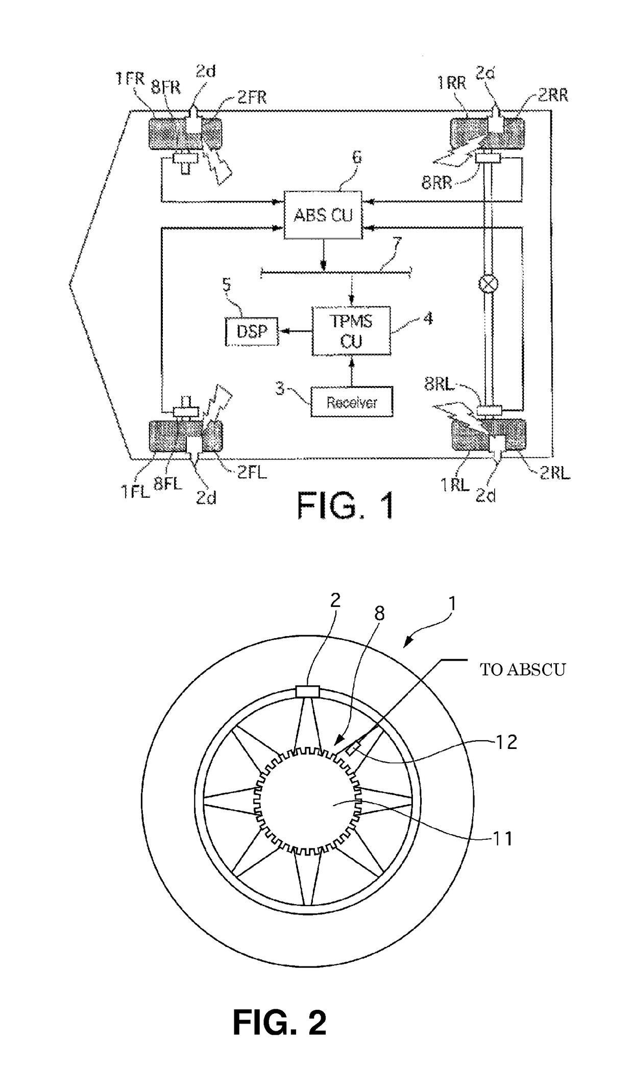
[0024]FIG. 1 is a configuration diagram illustrating a tire air or pneumatic pressure monitoring system 13 in a first embodiment. In this figure, the end letters annexed to each reference sign is intended to indicate as follows: FL stands for the left front wheel, FR stands for the right front wheel, RL stands for the left rear wheel, and RR stands for the right rear wheel, respectively. In the following description, when not specifically necessary, the description of FL, FR, RL and RR will be omitted.

[0025]The tire air pressure monitoring device 13 in the first embodiment is provided with TPMS (Tire Pressure Monitoring System) sensors 2 and a TPMS main unit 14. The TPMS main unit 14 is provided with a receiver 3, a TPMS control unit 4, a display 5, and an ABS (Antilock Brake System) control unit 6, and a wheel speed sensors 8.

[0026]FIG. 2 shows a wheel 1. As shown in FIG. 2, the TPMS sensor 2 is installed on each of the wheels 1 at an air valve position near the outer circumferenti...


PUM


Abstract

Provided is a tire air pressure transmission device configured to determine the rotational position of the tire air pressure transmission device based on a gravitational acceleration component of a centrifugal acceleration at the time of transmission of the tire air pressure information and to transmit in a wireless signal and at a prescribed cycle, tire air pressure information and tire air pressure transmission device rotational position information.

Description

CROSS-REFERENCE TO RELATED APPLICATION[0001]This national stage application claims priority to Japanese Patent Application No. 2011-108053 filed on May 13, 2011, which is incorporated herein in its entirety.TECHNICAL FIELD[0002]The present invention relates to a tire air pressure monitoring systemBACKGROUND[0003]In a tire air or pneumatic pressure monitoring device described in Japanese Patent Application Publication No. 2010-122023, TPMS (tire pressure monitoring system) data is transmitted at a time at which an acceleration in a rotational direction of a TPMS sensor installed on each wheel reaches “1” [G] or “−1” [G] so that a TPMS sensor transmits the TPMS data at a constant rotational position of a wheel. A TPMS control unit installed on a side of a vehicle body determines a wheel position of the TPMS sensor based on the number of teeth that are acquired from a chain of wheel speed pulses detected by a wheel speed sensor at a timing at which the TPMS data has been received.[0004...

Claims


Application Information

Patent Timeline
Patent Type & Authority Patents(United States)
IPC IPC(8): G01M17/02B60C23/04
CPCG01M17/02B60C23/04B60C23/0489B60C23/0459B60C23/0488B60C23/0416
Inventor SHIMA, TAKASHISAKAGUCHI, KAZUOTERADA, SYOJI
Owner NISSAN MOTOR CO LTD
Features
  • R&D
  • Intellectual Property
  • Life Sciences
  • Materials
  • Tech Scout
  • Unparalleled Data Quality
  • Higher Quality Content
  • 60% Fewer Hallucinations
Learn More