Envelope tracking with low frequency loss correction

a low frequency loss correction and envelope tracking technology, applied in gated amplifiers, process and machine control, instruments, etc., can solve the problems of inability to improve the efficiency of a power amplifier at near-dc low frequencies, and the coupling capacitors are typically blocked in the vicinity of dc low frequencies. achieve the effect of improving the efficiency of a power amplifier

Active Publication Date: 2017-11-28
SKYWORKS SOLUTIONS INC
View PDF12 Cites 88 Cited by
  • Summary
  • Abstract
  • Description
  • Claims
  • Application Information

AI Technical Summary

Benefits of technology

[0008]In accordance with some implementations, the present disclosure relates to a low frequency loss correction circuit that improves the efficiency of a power amplifier at near-DC low frequencies The low frequency loss correction circuit can include a signal error detection circuit configured to produce an error signal in response to detecting one or more frequency components of a tracking signal below a cutoff frequency that are substantially attenuated through a capacitive path. The low frequency loss correction circuit can include a drive circuit configured to convert the error signal into a low frequency correction signal, and provide the low frequency correction signal to a voltage supply line, the low frequency correction signal including at least some of the one or more frequency components of the tracking signal below a cutoff frequency that are substantially attenuated through the capacitive path.

Problems solved by technology

However, because of the finite size of the coupling capacitor, near-DC low frequencies are also typically blocked by the coupling capacitor along with the DC voltage level of the envelope tracking circuitry.
As a result, the efficiency of a power amplifier at near-DC low frequencies cannot be improved by envelop tracking using known methods and circuit arrangements because of the finite limitations of coupling capacitors.

Method used


Image

  • Envelope tracking with low frequency loss correction
  • Envelope tracking with low frequency loss correction
  • Envelope tracking with low frequency loss correction

Examples


Embodiment Construction

[0042]The headings provided herein, if any, are for convenience only and do not necessarily affect the scope or meaning of the claimed invention.

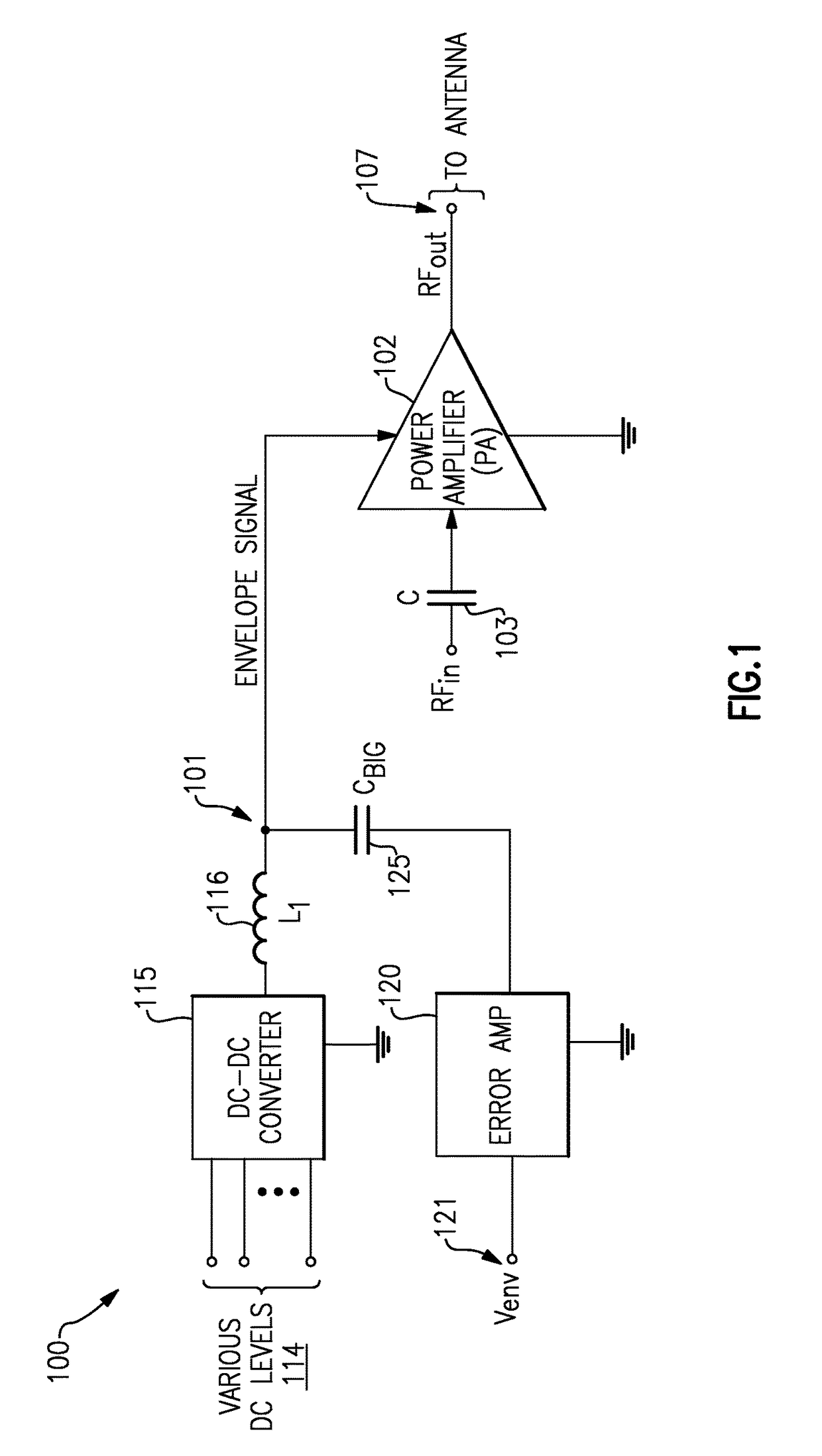
[0043]Power amplifiers are used in communication networks to set the transmission level of data signals. For example, power amplifiers are used to set transmission pulse laser energy in optical communication networks. Power amplifiers are used in radio frequency (RF) components of wireless devices—e.g., base stations and mobile devices—to set the power level transmitted through an antenna. Power amplifiers are also used in local area networks to support connectivity of servers, computers, laptops, and peripheral devices.

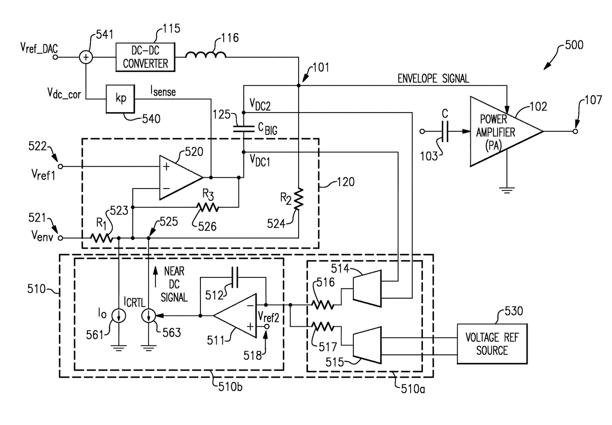
[0044]Managing power amplifier (PA) operation is a concern in mobile devices because the efficiency of a PA often significantly affects the battery life of a mobile device. Envelope tracking can be used to improve PA efficiency, and includes adjusting the voltage supplied to a PA in association with the envelope of the RF si...


PUM


Abstract

A low frequency loss correction circuit that improves the efficiency of a power amplifier at near-DC low frequencies The low frequency loss correction circuit can include a signal error detection circuit configured to produce an error signal in response to detecting one or more frequency components of a tracking signal below a cutoff frequency that are substantially attenuated through a capacitive path. The low frequency loss correction circuit can include a drive circuit configured to convert the error signal into a low frequency correction signal, and provide the low frequency correction signal to a voltage supply line, the low frequency correction signal including at least some of the one or more frequency components of the tracking signal below a cutoff frequency that are substantially attenuated through the capacitive path.

Description

CROSS-REFERENCE TO RELATED APPLICATION(S)[0001]This application claims priority to U.S. Provisional Application No. 62 / 030,224 filed Jul. 29, 2014, entitled ENVELOPE TRACKING WITH LOW FREQUENCY LOSS CORRECTION, the disclosure of which is hereby expressly incorporated by reference herein in its entirety.BACKGROUND[0002]Field[0003]The present disclosure generally relates to wireless communication systems and, more specifically, to improving the efficiency of power amplifiers therein.[0004]Description of the Related Art[0005]Power amplifiers are widely used in various communication networks to set the transmission power level of an information-bearing signal transmitted by a device. For example, power amplifiers are used to set the pulse energy emitted by pulsed lasers in optical communication networks. Power amplifiers are also used in the radio frequency (RF) front end components of wireless carrier network devices—such as base stations, repeaters, and mobile devices—to set the power...

Claims


Application Information

Patent Timeline
Patent Type & Authority Patents(United States)
IPC IPC(8): H03F3/191H02M3/155H03F3/68H03F3/72H03F3/45H03F3/24H03F3/195H03F3/08H03F1/02H03F3/04H03G3/20H02M1/00
CPCH03F1/0216H03F1/025H03F1/0222H03F1/0227H03F1/0255H03F1/0277H03F3/082H03F3/195H03F3/245H03F3/45071H03F3/68H03F3/72H02M3/155H03F2203/7236H02M2001/0045H03F2200/102H03F2200/111H03F2200/429H03F2200/504H03F2200/511H03F2200/555H03F2200/78H03F2203/7209H03F2203/7221H02M1/0045
Inventor BALTEANU, FLORINEL G.MACEDO, JOSE ALEJANDROPOPPLEWELL, PETER HARRIS ROBERTPINGOT, JAKUB F.
Owner SKYWORKS SOLUTIONS INC
Why Eureka
Try Eureka