Speaker sound hole device

a sound hole and speaker technology, applied in the direction of transducer details, electrical transducers, electrical apparatus, etc., can solve the problems of affecting the time needed for product debugging is long, and the cost of the product adopted this scheme is relatively high, so as to improve the performance of the product and tone quality, the effect of maximizing the sound channel and improving production efficiency

Active Publication Date: 2017-11-28
GOERTEK INC
View PDF9 Cites 3 Cited by
  • Summary
  • Abstract
  • Description
  • Claims
  • Application Information

AI Technical Summary

Benefits of technology

[0006]In view of the above problems, the objective of the present application is to provide a speaker sound hole device to solve the problems of high cost, long debugging time of the product performance, poor sound effects, and low product efficiency of the speaker products.
[0016]As can be seen from the above technical scheme, in the speaker sound hole device provided by the present application, the design of the front cover of the speaker unit may be optimized in such a way that open grooves are provided on the front cover so as to match with the module housing, which enables the front cavity to emit sound more smoothly, and enables the maximization of the sound channel in the case of the limitation on the overall height of the module, thus improving the performance of the products and tone quality; and the embedded structure of the speaker unit which is applied to the module housing emitting sound at lateral side enables that the module housing may be assembled with the speaker unit directly, thereby improving production efficiency and lowering costs.

Problems solved by technology

However, when such an integrated design for emitting sound at a lateral side is adopted, the height space of the module emitting sound at a lateral side is relatively lower, and since the module emitting sound at a lateral side is directly mounted in the speaker unit, the channel for emitting sound of the front cavity is relatively smaller, which affects the performance of the product, and the cost of the product adopted this scheme is relatively high, and the time needed for the product debugging is long, and thus the production efficiency of the product is affected.

Method used


Image

  • Speaker sound hole device
  • Speaker sound hole device
  • Speaker sound hole device

Examples


Embodiment Construction

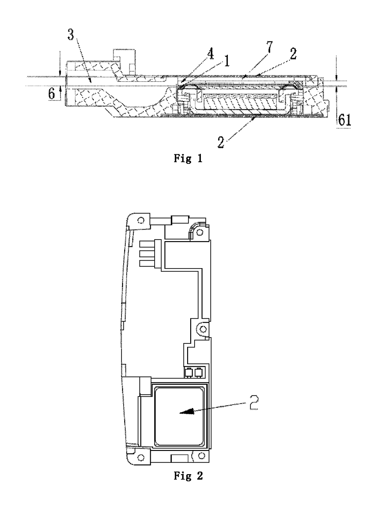
[0025]In the existing integrated design for the speaker emitting sound at lateral side, the front cover of the speaker unit is a traditional front cover, and meanwhile, the height of the space of the module housing is relatively lower, and the speaker unit is directly mounted into the module housing, and at this time, the front cover of the speaker unit and the module housing form a front cavity and a sound channel. The distance between the top and the bottom of the sound channel is 0.32 mm, and the sound channel formed by this means is relatively smaller, which will affect the sound effect of the speaker.

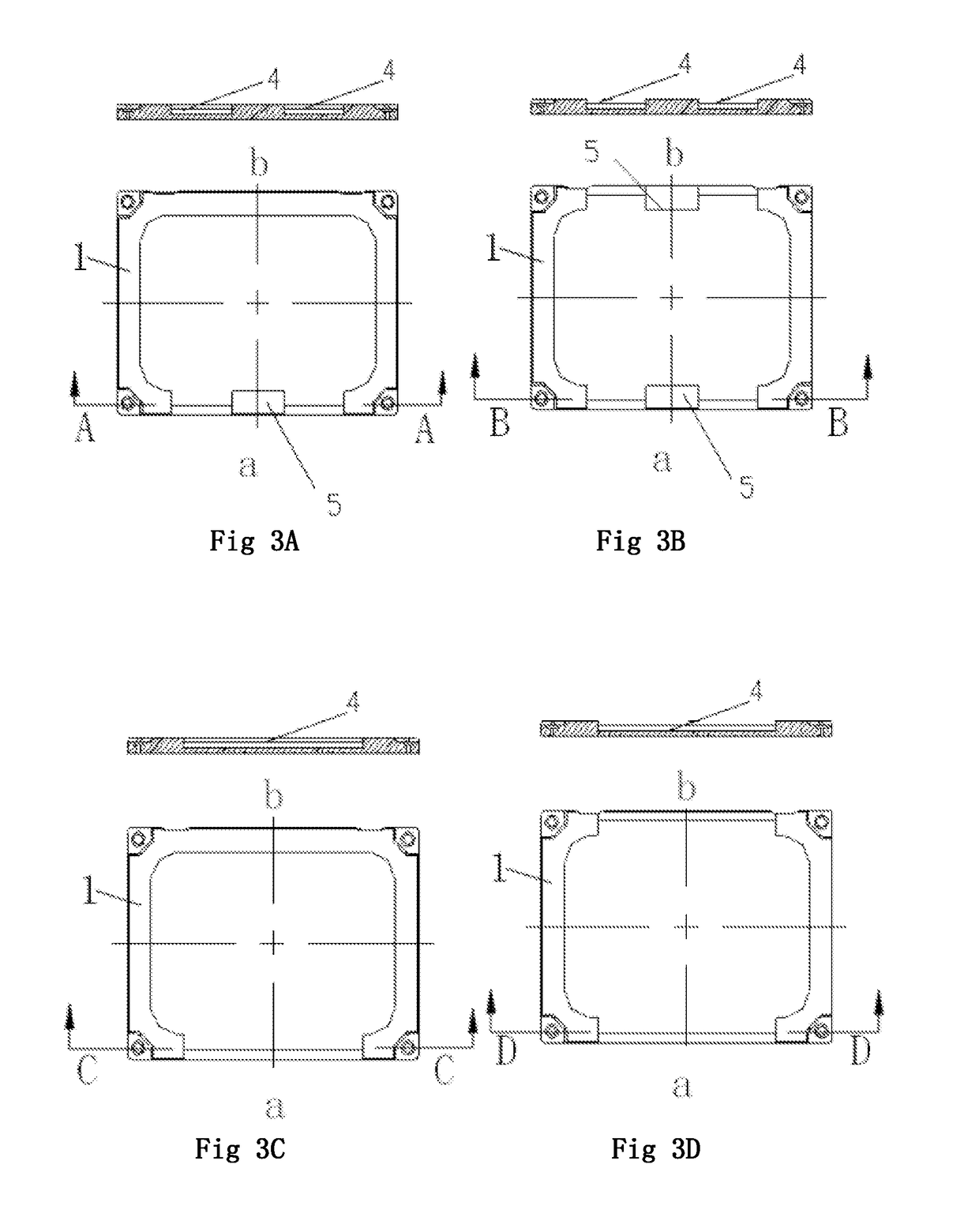
[0026]In the present application, the front cover of traditional speaker unit is improved in view of the above mentioned problem existing in the prior art, that is, open grooves are provided at the long side or short side of the front cover of the speak unit, and the front cover of the speaker unit provided with open grooves and the module housing are correspondingly matched with e...


PUM


Abstract

A speaker sounding hole device includes a speaker single-unit front cover and a module housing. The speaker single-unit front cover is rectangular, the long edges and / or short edges of the speaker single-unit front cover are provided with open grooves, and the speaker single-unit front cover and the module housing are correspondingly assembled by means of the open grooves. The speaker single-unit front cover provided with the open grooves and the module housing form a front cavity of the speaker sounding hole device. Spaces formed by the open grooves are connected with the front cavity of the speaker sounding hole device to form a sounding channel of the speaker sounding hole device. The device can solve the problems of high cost, long tuning time of the product performance, poor sounding effects and low product efficiency.

Description

TECHNICAL FIELD[0001]The present disclosure relates to the technical field of acoustoelectric conversion, more specifically, to a speaker sound hole device.BACKGROUND ART[0002]With the social progress and technical development, electronic products, such as cell phones and TVs, become smaller in size and gradually thinned in recent years, and the requirements for the performance of the electronic products become more and more critical, and thus, the related electronic parts of the electronic products are required to be smaller in size and thickness and improved in performance and consistency.[0003]For appearance structure, speaker modules of the electronic products, such as, cell phones, TVs and the like, should be designed with a structure emitting sound at a lateral side, and an integrated design for emitting sound at a lateral side is usually adopted so as to improve the performance of the speaker and improve its sound quality due to the limitation of the overall height of the pro...

Claims


Application Information

Patent Timeline
Patent Type & Authority Patents(United States)
IPC IPC(8): H04R1/02H04R1/28H04R1/32
CPCH04R1/2803H04R1/323H04R2499/11H04R1/2849H04R1/025
Inventor ZHANG, JUNZHANG, CHENGFEIYANG, XINFENG
Owner GOERTEK INC
Why Eureka
Try Eureka