Converter control system

a control system and converter technology, applied in the direction of electric variable regulation, process and machine control, instruments, etc., can solve the problems of time-consuming and time-consuming circuit re-design, and achieve the effect of effectively solving the shortcomings

Active Publication Date: 2017-12-19
JOINT POWER EXPONENT
View PDF38 Cites 0 Cited by
  • Summary
  • Abstract
  • Description
  • Claims
  • Application Information

AI Technical Summary

Benefits of technology

[0014]By providing the converter control system of the present invention to re-program according to different operation modes, the time-consuming redesign of the circuits would be thus avoided. In addition, upon judging the difference between the average value and the real-time feedback value, the duty cycle can be adjusted in time according to the heavy load or the light load, such that phenomena of overshoot and load drop in the converter can be effectively avoided.

Problems solved by technology

In view that the conventional technique is to use the analog circuit to control the load switch, thus, under the framework of the analog circuit, revising the circuit, which is time-consuming, is necessary to meet a change in operation mode.

Method used


Image

  • Converter control system
  • Converter control system
  • Converter control system

Examples


Embodiment Construction

[0022]The invention disclosed herein is directed to a converter control system. In the following description, numerous details are set forth in order to provide a thorough understanding of the present invention. It will be appreciated by one skilled in the art that variations of these specific details are possible while still achieving the results of the present invention. In other instance, well-known components are not described in detail in order not to unnecessarily obscure the present invention.

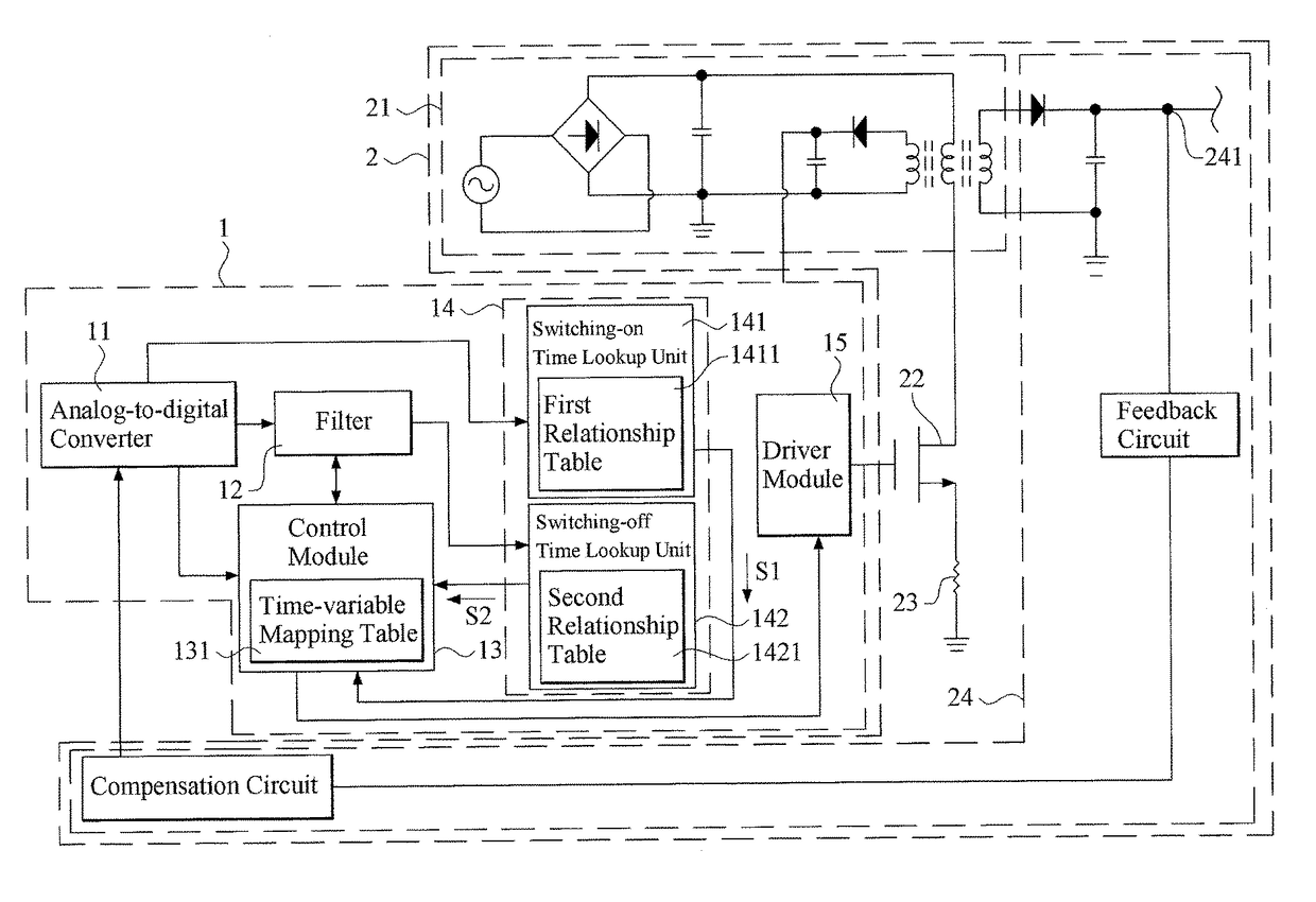
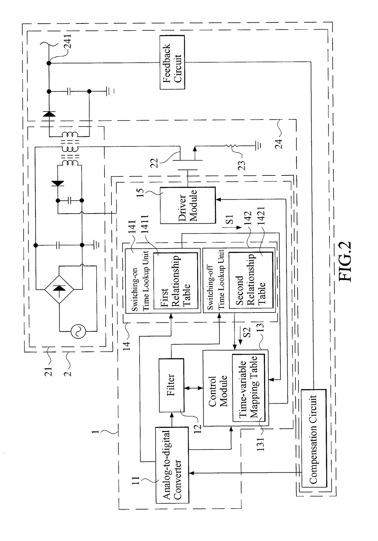
[0023]Referring now to FIG. 2, a schematic view of a preferred embodiment of the converter control system in accordance with the present invention, which is connected with a converter, is shown.

[0024]As shown, the preferred converter control system 1 is electrically coupled with a converter 2. The converter 2 can be, but not limited to, a flyback converter. The converter 2 includes an input level circuit 21, a load switch 22, a load resistor 23 and an output level circuit 24. The input l...


PUM


Abstract

A converter control system includes an analog-to-digital converter, a filter and a control module. The analog-to-digital converter digitalizes a different-time and a real-time feedback voltage. The filter bases on the different-time feedback voltage to sample a historical average feedback voltage. The control module receives the real-time feedback voltage, bases on the historical average feedback voltage to detect a load status of the converter, and bases on the real-time feedback voltage and the historical average feedback voltage to derive a voltage difference. The control module applies a control duty cycle to control the load switch. While the control module detects that the load status switches to a heavy-load status and the voltage difference reaches the threshold voltage, the control duty cycle is increased. While the control module detects that the load status switches to the light-load status and the voltage difference reaches the threshold voltage, the control duty cycle is decreased.

Description

[0001]This application claims the benefit of Taiwan Patent Application Serial No. 104130941, filed Sep. 18, 2015, the subject matter of which is incorporated herein by reference.BACKGROUND OF INVENTION[0002]1. Field of the Invention[0003]The invention relates to a converter control system, and more particularly to the converter control system that introduces digital circuits to control and adjust duty cycles according to the light-load status and the heavy-load status.[0004]2. Description of the Prior Art[0005]With progress in modern technology, various electronic devices have become necessities to people's daily life. Also, as rising demands in energy saving and environment preservation upon consumer electronics, low power consumption for an idle state of the electronic product so as to extend service life of batteries and to reduce the consumption of electricity has been one of basic requirements for designing a converter in this industry.[0006]Referring to FIG. 1, a schematic vie...

Claims


Application Information

Patent Timeline
Patent Type & Authority Patents(United States)
IPC IPC(8): H02M3/335H02M1/00
CPCH02M3/33507Y02B70/16H02M2001/0032H02M1/0032Y02B70/10
Inventor LAI, JYH-TING
Owner JOINT POWER EXPONENT
Why Eureka
Try Eureka