Imaging display device and control method thereof

a display device and display device technology, applied in the direction of television system, solid-state device signal generator, picture signal generator, etc., can solve the problems of generating a gap between the timing of the displayed object image and the timing of the actual imaged still image, and causing a considerable delay. to achieve the effect of shortening the time delay from imaging

Active Publication Date: 2017-12-19
SEIKO EPSON CORP
View PDF14 Cites 0 Cited by
  • Summary
  • Abstract
  • Description
  • Claims
  • Application Information

AI Technical Summary

Benefits of technology

[0010]An advantage of some aspects of the invention is to control delay from imaging to displaying, even if the optical properties of the lens change, in accordance with the change in the optical properties.
[0012]According to the aspect of the invention, since image processing is performed in accordance with the optical properties of the lens unit, the time required for the image processing fluctuates if the optical properties of the lens unit change, while, since the timing control unit changes a phase difference from the frame start of the imaging signal to the frame start of the image signal in accordance with the optical properties of the lens unit, it is possible to shorten the time delay from imaging to displaying compared to the case where the phase difference is fixed.
[0016]According to the aspect of the invention, even if the lens unit is exchanged, it is possible to specify the aberration of the lens unit by the identifying data for identifying the type of the lens unit, and thus it is possible to determine the phase difference considering the time required for the correction processing of the aberration. Because of this, compared to the case where the phase difference is fixed, it is possible to shorten the time delay from imaging to displaying by changing the phase difference in accordance with the type of the lens unit.
[0018]According to the aspect of the invention, since it is possible to determine the phase difference in accordance with at least one of zooming rate, focal length, and diaphragm value, it is possible to properly set the time delay from imaging to displaying, in the case where the aberration of the lens unit generated in accordance with these optical properties is corrected, even if the time required for the aberration correction processing changes.
[0022]According to the aspect of invention, since image processing is performed in accordance with the optical properties of the lens unit, the time required for the image processing fluctuates if the optical properties of the lens unit change, while, since a phase difference from the frame start of the imaging signal to the frame start of the image signal is changed in accordance with the optical properties of the lens unit, it is possible to shorten the time delay from imaging to displaying compared to the case where the phase difference is fixed.

Problems solved by technology

However, in this live view, considerable delay is caused from imaging the object by an image sensor to displaying on the view finder or the like.
Because of this, it is difficult to allow the camera to follow a moving object.
Moreover, if an instruction of imaging of a still image based on the displayed object image is given, a gap is generated between the timing of the displayed object image and the timing of the actually imaged still image.
In particular, in a case where the objects move fast, it is difficult to image an intended still image.
Meanwhile, in a lens used in an imaging display device, if there is a lens with great lens distortion or chromatic aberration, there is also a lens in which such aberration is small.
However, there is a case where the extent of lens distortion changes in accordance with the zooming rate.
In particular, in an imaging display device capable of exchanging a lens as in a so-called single lens reflex camera, since the optical properties of a lens for exchange that will be released in the future are unknown, there is a problem that the phase difference cannot be properly set.
Moreover, if the display vertical synchronization signal is first generated, the display vertical synchronization signal is delayed, and the image vertical synchronization signal is generated, it is not possible to generate an imaging signal and to display an image right after power is supplied regardless of the imaging unit being operable.

Method used


Image

  • Imaging display device and control method thereof
  • Imaging display device and control method thereof
  • Imaging display device and control method thereof

Examples


application examples

4. Application Examples

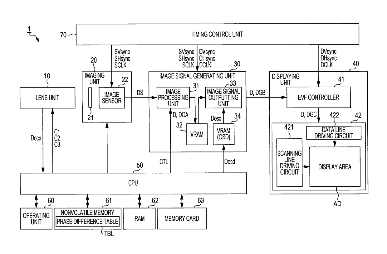
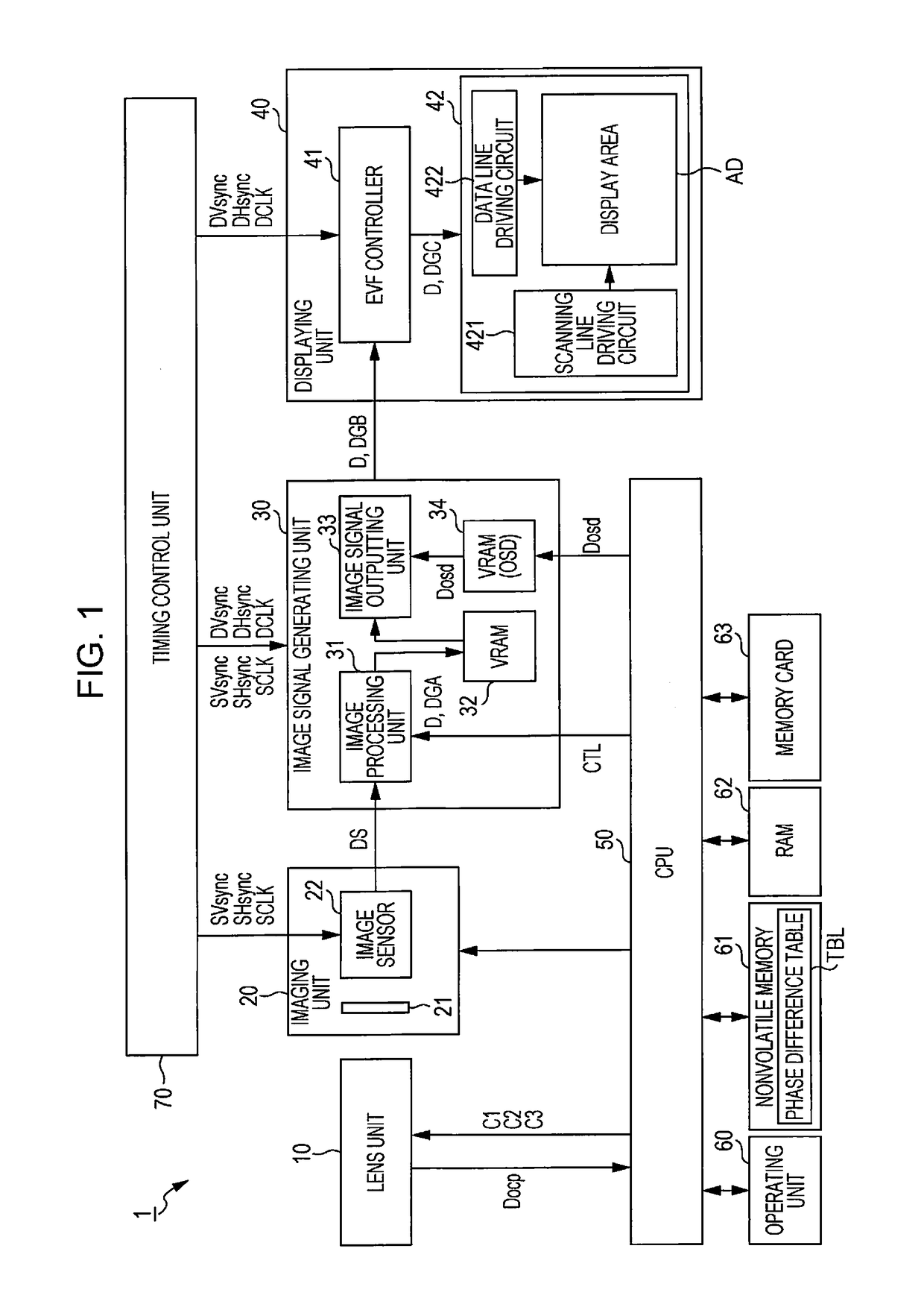
[0129]In the above-described embodiment, the imaging display device 1 is described as one example of a mirrorless digital single lens reflex camera. However, the imaging display device 1 can be applied to various electronic apparatuses.

application example 1

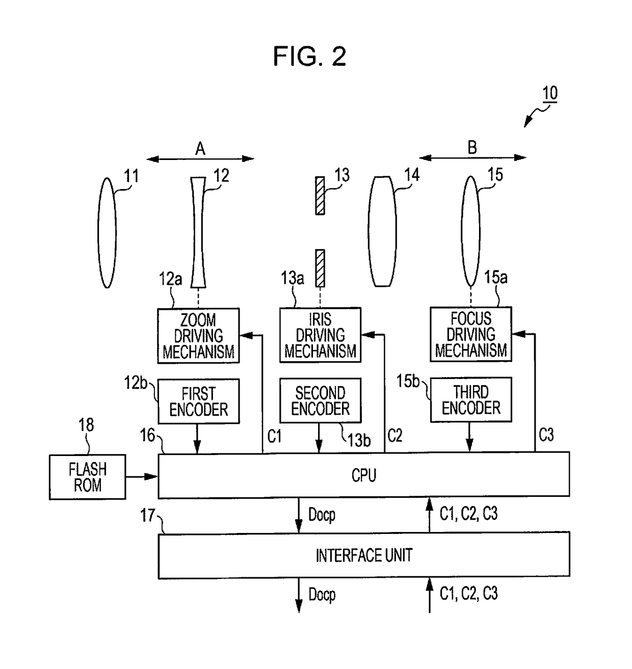
[0130]The imaging display device 1 can be applied to a digital camera of which the lens unit 10 is not exchangeable. In this case, the content of the aberration correction processing and the phase difference TD may be determined in accordance with at least one of the parameters related to the optical properties of the lens unit 10 such as focal length, zooming rate, diaphragm value, or focus value. In addition, for example, in a digital camera in which a manual function in which zoom, focus, iris, or the like is determined by the operation by the user is not equipped but zoom, focus, iris, or the like is set by the control from the main body side, as long as these parameters can be obtained in the main body, there is no need for transmitting the optical property data Docp from the lens unit 10.

application example 2

[0131]The imaging display device 1 can be applied to an electronic binocular or an electronic telescope of which the magnification is changeable. In this case, in accordance with the magnification (parameter related to the optical properties of the lens), the content of the aberration correction processing changes, and it is possible to minimize the time delay from imaging to displaying by deciding the phase difference TD according thereto.


PUM


Abstract

An imaging display device includes a lens unit, an imaging unit that outputs an imaging signal obtained by imaging, an image signal generating unit that generates an image signal by performing image processing in accordance with optical properties of the lens unit, a display unit that displays an image based on the image signal, and a timing control unit that controls the phase difference from the frame start of the imaging signal to the frame start of the image signal so as to be changed in accordance with a predetermined time required for the image processing.

Description

BACKGROUND[0001]1. Technical Field[0002]The present invention relates to an imaging display device and a control method thereof.[0003]2. Related Art[0004]In a so-called mirrorless digital camera, an image of an object can be confirmed by a so-called live view operation in which an image in accordance with an image signal imaged by a charged coupled device (CCD) image sensor, a complementary metal-oxide semiconductor (CMOS) image sensor, or the like is displayed on a liquid crystal panel provided on the housing rear surface, an electronic view finder (hereinafter, referred to as EVF) attached to a housing upper portion, or the like in real time.[0005]However, in this live view, considerable delay is caused from imaging the object by an image sensor to displaying on the view finder or the like. Because of this, it is difficult to allow the camera to follow a moving object. Moreover, if an instruction of imaging of a still image based on the displayed object image is given, a gap is ge...

Claims


Application Information

Patent Timeline
Patent Type & Authority Patents(United States)
IPC IPC(8): H04N5/238H04N5/232H04N5/345H04N9/04
CPCH04N5/238H04N5/23293H04N5/3456H04N5/3458H04N5/3452H04N9/045H04N23/63H04N25/441H04N25/445H04N25/447H04N23/10H04N25/134H04N23/75
Inventor SHIOHARA, RYUICHI
Owner SEIKO EPSON CORP
Why Eureka
Try Eureka