

Facility display unit
a technology of display unit and display screen, which is applied in the direction of navigation instruments, maps/plans/charts, instruments, etc., can solve the problems of hindering the user from grasping an overall picture of the facility with ease, and the user is not able to freely set the display mode of the facility, so as to achieve the effect of grasping an overall picture of the facility
- Summary
- Abstract
- Description
- Claims
- Application Information
AI Technical Summary
Benefits of technology
Problems solved by technology
Method used
Image

Examples
embodiment 1
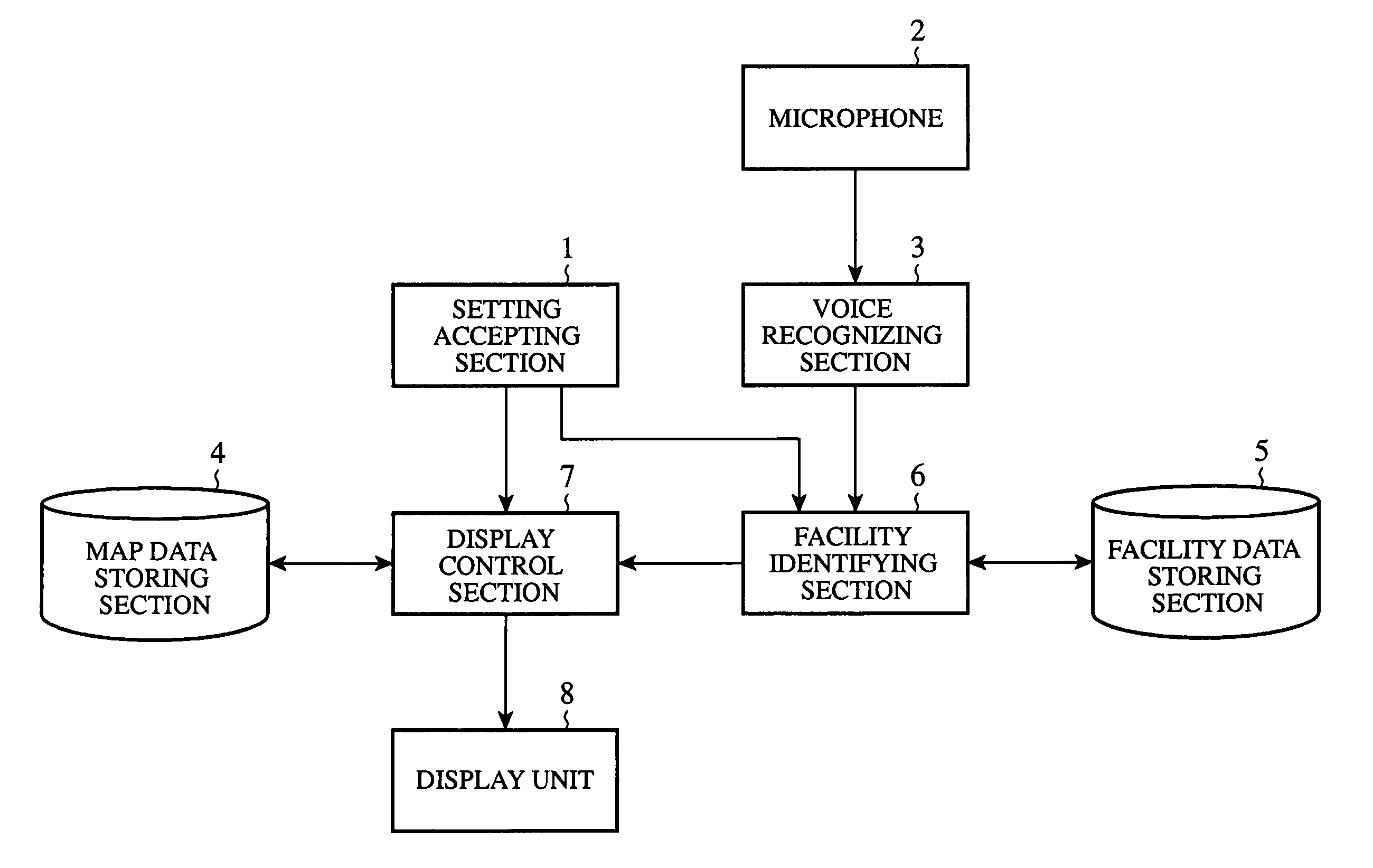
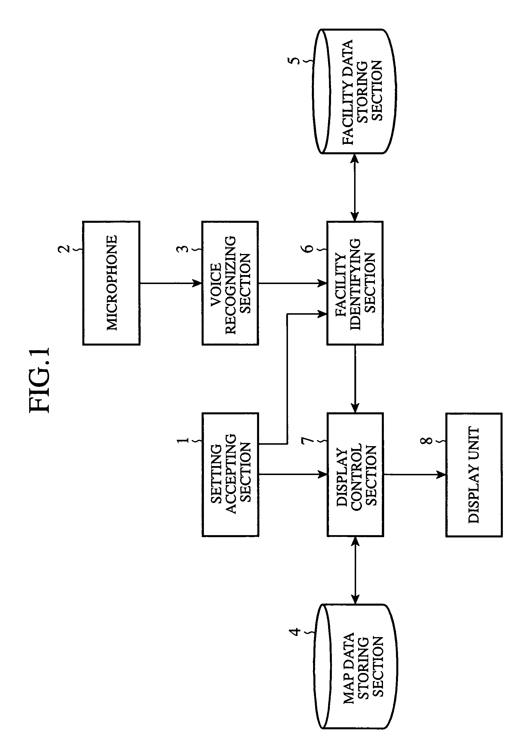
[0030]FIG. 1 is a block diagram showing a configuration of the facility display unit of an embodiment 1 in accordance with the present invention. In FIG. 1, a setting accepting section 1 is composed of an external interface for receiving an operation signal such as infrared rays transmitted from a remote control, or a man-machine interface such as key switches for accepting the operation of a user. The user utilizes the setting accepting section 1 for carrying out a variety of settings such as setting a destination and the display mode of the facilities.
[0031]The setting accepting section constitutes a setting means.
[0032]A microphone 2 receives the speech of the user. A voice recognizing section 3 carries out recognition processing of the speech of the user input to the microphone 2.
[0033]A map data storing section 4 is a memory that stores map data for three-dimensional display and map data for two-dimensional display. A facility data storing section 5 is a memory that stores imag...
embodiment 2
[0072]The foregoing embodiment 1 is described by way of example in which the display control section 7 three-dimensionally displays the image of the facilities on the wide-area map according to the image data on the facilities retrieved by the facility identifying section 6, followed by gradually zooming in on the image of the facilities. After that, the display control section 7 can further zoom in on the image of the facilities, which have been zoomed in, in response to an enlarged display request of the facilities from the user. Alternatively, the display control section 7 can make enlarged display of specific objects in the facilities (such as commodities).
[0073]More specifically, when the user inputs the enlarged display request of the facilities by operating the setting accepting section 1, or when the voice recognizing section 3 recognizes the speech of the user (steps ST31 and ST32 of FIG. 10), and the recognition result of the speech is “enlarge facilities”, for example (st...
embodiment 3
[0076]FIG. 11 is a block diagram showing a configuration of the facility display unit of an embodiment 3 in accordance with the present invention. In FIG. 11, since the same reference numerals designate the same or like portions to those of FIG. 1, their description will be omitted here.
[0077]A setting accepting section 9 accepts the setting of the destination and the setting of the display mode of the facilities just as the setting accepting section 1 of FIG. 1. In addition, it also accepts the settings of a zoom-in rate of the image of the facilities and the rotation speed of the image of the facilities.
[0078]Although the foregoing embodiment 1 is described by way of example in which the display control section 7 zooms in on the image of the facilities and rotates the image of the facilities, this is not essential. For example, the display control section 7 can zoom in on and rotate the image of the facilities at the zoom-in rate and the rotation speed set by the setting accepting...
PUM
 Abstract
Description
Claims
Application Information