Patient tables and magnetic resonance imaging equipment

a technology of magnetic resonance imaging and patient tables, applied in the field of patient tables, can solve the problems of time-consuming and power-consuming operation, patient may only be examined, and the efficiency of the manual motion mechanism is relatively low, so as to and reduce or eliminate the risk of generating an uncontrollable

Active Publication Date: 2017-12-26
SIEMENS HEALTHCARE GMBH
View PDF18 Cites 0 Cited by
  • Summary
  • Abstract
  • Description
  • Claims
  • Application Information

AI Technical Summary

Benefits of technology

[0011]The present embodiments may obviate one or more of the drawbacks or limitations in the related art. For example, in some embodiments, a patient platform that uses a minimum of lifting motion operating force is provided. In some embodiments, the patient platform is widely applicable to various types of imaging equipment (e.g., MRI), and has a structure that is simple, inexpensive, and easy to operate.
[0037]In some embodiments (e.g., for use in nuclear magnetic resonance imaging equipment), the spring structure is arranged horizontally. As a result of the horizontal extension orientation of the spring structure, the influence of the magnetism of the spring structure on the homogeneity of the system static magnetic field may be reduced to an acceptable degree (e.g., such that the influence on the static field is not sufficient to result in the loss of imaging function). In addition, during replacement of components, the spring structure may not be extensively affected by the magnetic field, thereby reducing or eliminating the risk of generating an uncontrollable magnetic force and potential safety hazards. Moreover, a conventional magnet configuration may be selected for the nuclear magnetic resonance components.

Problems solved by technology

Due to limitations of physical condition of the patient, the patient may only be examined when lying down on the patient table.
The efficiency of the manual motion mechanism is relatively low, and the operation is time-consuming and power-consuming.

Method used


Image

  • Patient tables and magnetic resonance imaging equipment
  • Patient tables and magnetic resonance imaging equipment
  • Patient tables and magnetic resonance imaging equipment

Examples


Embodiment Construction

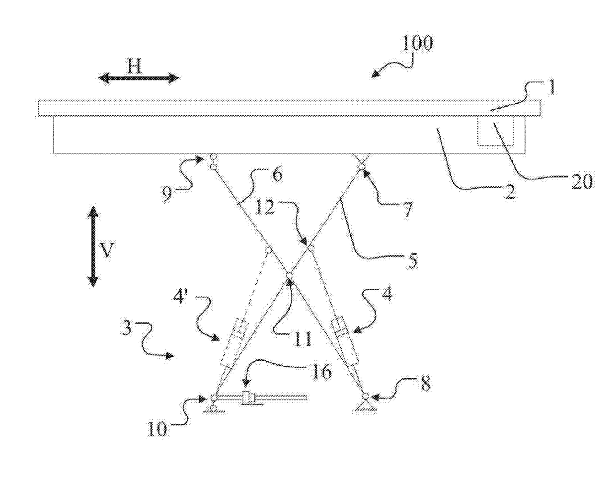
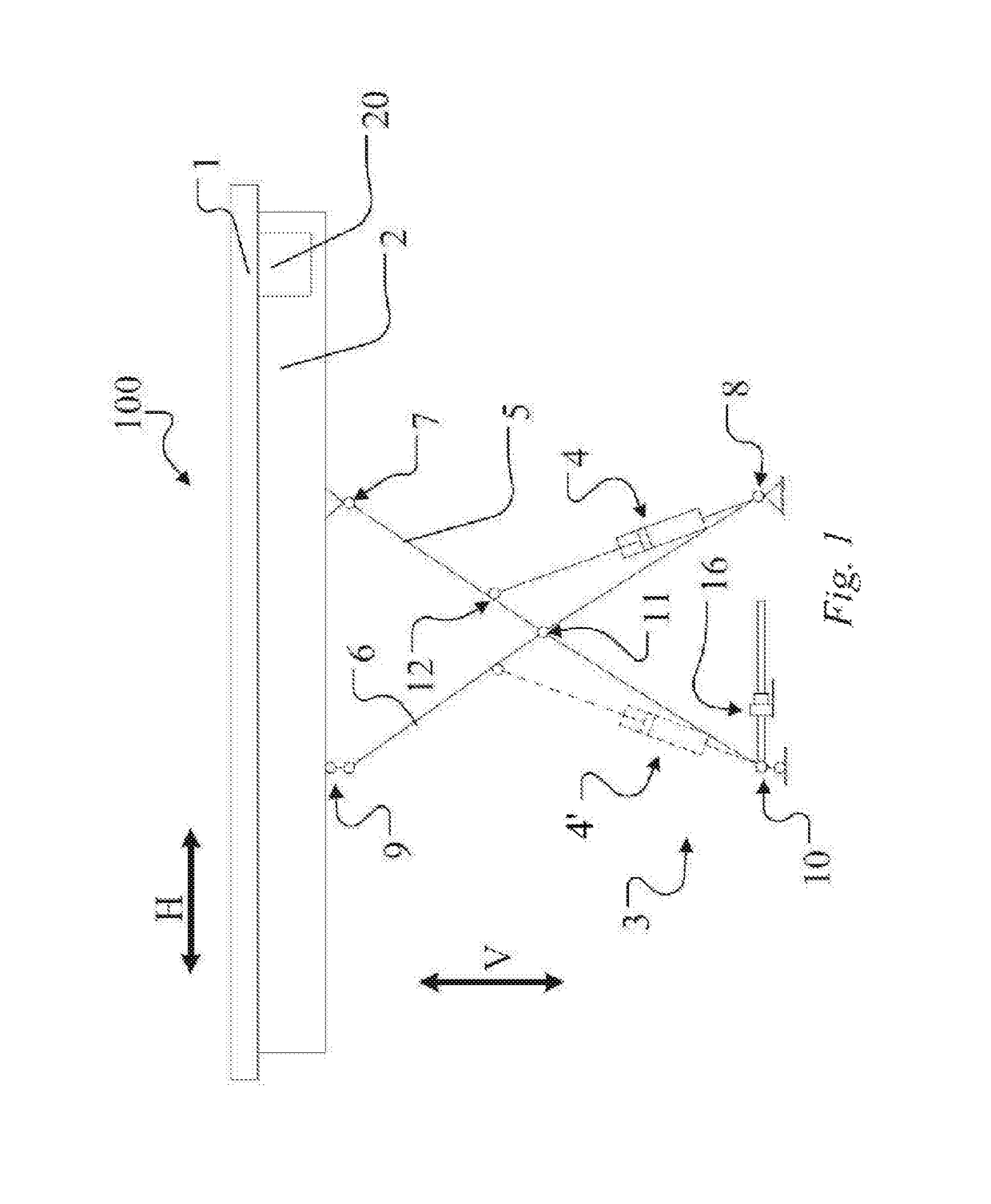
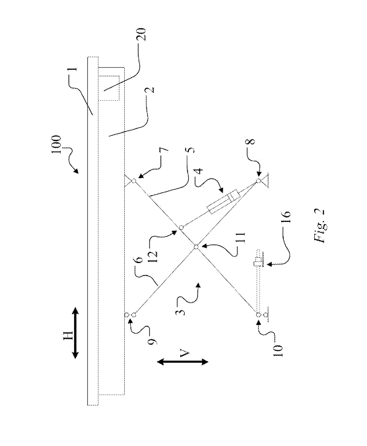
[0047]Exemplary embodiments will now be described with reference to the accompanying drawings. Although the accompanying drawings are provided to illustrate exemplary implementations in accordance with the present teachings, the accompanying drawings may not reflect the actual size or shape of particular embodiments. In addition, for the sake of clarity, some features may be magnified, removed, partially sectioned or shown in schematic form. As used herein, the phrase “in the accompanying drawings” and similar expressions may not refer simultaneously to all of the accompanying drawings or examples.

[0048]As used herein, the directional terms used to describe the accompanying drawings (e.g., “above,”“under,”“left,”“right,”“upward,”“downward,” and the like) have their normal meanings. Unless otherwise indicated, the directional terms are intended to represent corresponding directions vis-à-vis the patient table and corresponding imaging equipment.

[0049]As used herein the terms “approxi...


PUM


Abstract

A patient table includes a table body configured for bearing a patient, a connecting rod structure configured for supporting the table body, and a spring structure. The connecting rod structure is operable such that the table body may perform a lifting motion between a high position and a low position. Both ends of the spring structure are fixed. At least a first end of the spring structure is hinged to the connecting rod structure. The spring structure may be used for driving the lifting motion of the connecting rod structure and / or bearing the table body. The patient table may be used for nuclear magnetic resonance imaging equipment.

Description

RELATED APPLICATIONS[0001]This application claims the benefit of Chinese Patent Application No. CN 201210591452.2, filed Dec. 31, 2012, the entire contents of which are hereby incorporated herein by reference.TECHNICAL FIELD[0002]The present teachings relate generally to patient tables (e.g., for use in imaging equipment, such as nuclear magnetic resonance imaging equipment) and to nuclear magnetic resonance imaging (MRI) equipment having such patient tables.BACKGROUND[0003]For many examinations that use imaging equipment such as nuclear magnetic resonance imaging (MRI) equipment, computed tomography (CT) equipment, and other X-ray examination equipment, the patient is lying down on a patient table (PTAB). Due to limitations of physical condition of the patient, the patient may only be examined when lying down on the patient table.[0004]At least a part of the patient table (e.g., a top board) may move horizontally. After the patient lies down on the patient table, the horizontally m...

Claims


Application Information

Patent Timeline
Patent Type & Authority Patents(United States)
IPC IPC(8): A61B5/05A61B5/055A61B5/00
CPCA61B5/704A61B5/0555A61B5/055
Inventor XUE, TING QIANGYAN, XU
Owner SIEMENS HEALTHCARE GMBH
Why Eureka
Try Eureka