Check patentability & draft patents in minutes with Patsnap Eureka AI!

Rapid autofocus method for stereo microscope

a stereo microscope and autofocus technology, applied in the field of stereo microscope focusing technology, can solve the problems of relatively time-consuming focusing process of the stereo microscope system, high equipment cost, and inability to choose the appropriate passive focusing method under different experimental conditions, and achieve rapid autofocus and short time. the effect of focusing and rapid autofocus

Inactive Publication Date: 2017-12-26
NINGBO UNIV
View PDF1 Cites 0 Cited by
  • Summary
  • Abstract
  • Description
  • Claims
  • Application Information

AI Technical Summary

Benefits of technology

The present invention provides a rapid autofocus method for stereo microscopes that uses binocular information from acquired images to quickly autofocus on a specific image. The method is efficient and saves time compared to prior art methods. Additionally, the method provides a definition for the image through an index, which helps to better understand and interpret the image. Overall, the invention provides a more efficient and effective way to autofocus stereo microscopic images.

Problems solved by technology

Since the equipments for the active focusing method are expensive, the passive focusing method becomes the current research trend.
A great amount of conventional passive focusing methods has been put forward, but it still remains uncertain as to choosing the appropriate passive focusing method under different experimental conditions.
Even if the optimal definition function is determined under the certain experimental condition, due to the lack of the fixed indexes for representing the nature of the images, each time of focusing still needs shooting a large quantity of clear and vague image sequences, which leads to the relatively time-consuming focusing process of the stereo microscope system.
However, the conventional passive focusing method does not judge whether an arbitrary image is clear or vague, and thus, the researchers merely tend to look for the clearest image, which also consumes much time.

Method used


Image

  • Rapid autofocus method for stereo microscope
  • Rapid autofocus method for stereo microscope
  • Rapid autofocus method for stereo microscope

Examples


Embodiment Construction

[0067]The present invention is further illustrated in combination of the drawings the preferred embodiment.

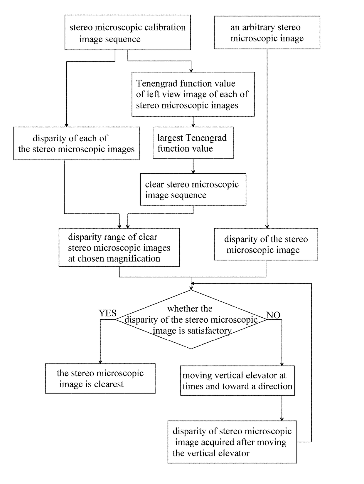
[0068]Referring to FIG. 1 of the drawings, according to a preferred embodiment of the present invention, a rapid autofocus method for a stereo microscopic comprises the following steps.

[0069]Step ①: acquiring a stereo microscopic calibration image sequence which has M stereo microscopic images, wherein: the M stereo microscopic images in the stereo microscopic calibration image sequence are orderly arranged from vague to clear and then from clear to vague, and contain the same target object; an i th stereo microscopic image in the stereo microscopic calibration image sequence is denoted as Ii; a left view image and a right view image of Ii are respectively denoted as IiL and IiR; M≧50. According to the preferred embodiment of the present invention, M=150; 1≦i≦M.

[0070]According to the preferred embodiment of the present invention, the step of acquiring the stereo microscopic cal...


PUM


Abstract

A rapid autofocus method for a stereo microscope includes steps of: calculating a disparity of each of stereo microscopic images in a stereo microscopic calibration image sequence; extracting a clear stereo microscopic image sequence from the stereo microscopic calibration image sequence; then, finding out a largest disparity and a smallest disparity among the disparities of all the stereo microscopic images in the clear stereo microscopic image sequence; at a chosen magnification, arbitrarily acquiring a stereo microscopic image; finally, determining a disparity range according to the disparity of the acquired stereo microscopic image, the largest disparity and the smallest disparity, and realizing an autofocus of a target object in the acquired stereo microscopic images. The disparity range is obtained via once off-line calibration at the same magnification, and applicable to the autofocus at an arbitrary timing.

Description

CROSS REFERENCE OF RELATED APPLICATION[0001]This invention claims priority under 35 U.S.C. 119(a-d) to CN 201510166716.3, filed Apr. 10, 2015.BACKGROUND OF THE PRESENT INVENTION[0002]Field of Invention[0003]The present invention relates to a stereo microscope focusing technology, and more particularly to a rapid autofocus method for a stereo microscope.[0004]Description of Related Arts[0005]Machine vision system is more and more widely applied in the fields of micro manufacture and inspection due to its reliability, relatively cheap price and high output. However, the machine vision system requires highly efficient image processing algorithm for extracting visual characteristics, which further requires the usage of high-quality clear images to guarantee the precision of the visual characteristics. In order to obtain clear images and take the fullest advantage of the potential of the microscope, it is very important to employ an efficient, precise, robust and rapid autofocus method t...

Claims


Application Information

Patent Timeline
Patent Type & Authority Patents(United States)
IPC IPC(8): G02B21/00G02B21/24G02B21/36G02B21/22
CPCG02B21/367G02B21/244G02B21/22
Inventor YU, MEILIU, YICUI, LIFAN, SHENGLIWANG, YIGANG
Owner NINGBO UNIV
Features
  • R&D
  • Intellectual Property
  • Life Sciences
  • Materials
  • Tech Scout
  • Unparalleled Data Quality
  • Higher Quality Content
  • 60% Fewer Hallucinations
Learn More