Transporting arrangement

a technology of transport arrangement and arrangement, applied in the direction of dynamo-electric components, dynamo-electric machines, non-mechanical conveyors, etc., to achieve the effect of convenient installation, reliable operation and cost-effectiveness

Active Publication Date: 2018-01-02
SYNTEGON TECHNOLOGY GMBH +1
View PDF22 Cites 7 Cited by
  • Summary
  • Abstract
  • Description
  • Claims
  • Application Information

AI Technical Summary

Benefits of technology

[0003]The transporting arrangement according to the invention ensures a very low-maintenance and reliable operation while at the same time being cost effectively manufactured and easy to install. The design of the transporting arrangement is therefore of as small a construction as possible; thus enabling the space requirements to be kept to a minimum. A compact design results from the special arrangement of the guide system and the motor plane, and the transporting units can pass through very tight radii at the same time. These advantages are achieved by the transporting arrangement according to the invention, comprising at least one guide system having a fixed guide rail and a plurality of supporting elements. The supporting elements are particularly designed in the form of rollers and / or sliders and / or as levitation elements, i.e. freely floating elements on which guide rails are carried. The transporting arrangement furthermore comprises a transporting unit. This transporting unit is connected to the supporting elements; thus enabling the transport unit to be guided on the guide rail and to be linearly movable in a movement direction. A linear motor drive arrangement provides for the drive of the transporting unit which can be individually actuated. To this end, the linear motor drive arrangement comprises a fixed stator unit. The stator unit extends by means of a plurality of coils parallel to the guide rail. In addition, the linear motor drive arrangement comprises at least one magnetic element on the transporting unit. This magnetic element is particularly a permanent magnet. By means of an appropriate actuation of the coils in the stator unit, a magnetic force acts on said magnetic elements of the transporting unit. As a result, the transporting units can be accelerated, decelerated and / or be positioned at rest. As seen in cross section, the guide system is disposed laterally with respect to the linear motor drive arrangement. A substantially vertical guide plane is defined, which at least approximately runs parallels to the movement direction and through the center of the guide system. A substantially vertical motor plane is furthermore defined, which is likewise aligned approximately parallel to the movement direction and runs through the center of the linear motor drive arrangement. A substantial proportion of the transporting unit, denoted as basic body, is arranged between the guide plane and the motor plane. This basic body preferably carries at least the supporting elements and at least one of the magnetic elements. A part of a measuring system can furthermore be arranged on said base body of the transporting unit, as will be explained later in detail.
[0006]The transporting arrangement preferably extends in a U-shaped manner across the stator unit. In so doing, a magnetic element can be disposed on each side of the stator unit of the transporting arrangement. As a result, an efficiently functioning linear motor is possible. The center of the linear motor drive arrangement is therefore the center between the two magnetic elements or, respectively, the center of the stator unit.
[0009]According to a second variant, the second measuring component is located on a further limb. The transporting unit thus extends in a U-shaped manner across the stator unit, wherein the basic body forms a limb, a further limb lying opposite thereto on the other side of the stator unit. The second measuring component preferably faces the motor plane. The second measuring component is particularly a contour milled into the further limb of the transporting unit. The second measuring component is alternatively mounted directly on the further limb or on said further limb via an intermediate piece. In so doing, the further limb is preferably designed shorter than the basic body. The further limb is therefore removed from the zone of influence of the measuring system; and the material thereof (electrically conductive or nonconductive) having relatively massive geometry does not influence or only slightly influences the measuring behavior. As a result, improved measuring results can be achieved, which positively affects the accuracy and movement quality of the system.
[0015]The transporting arrangement comprises a holding fixture for carrying a product or a driver for pushing a product. The holding fixture or, respectively, driver preferably lies on a different side of the motor plane than the guide plane. The two different centers of mass in the loaded and unloaded state result from this very asymmetrical arrangement. By virtue of the fact that the holding fixture or the driver essentially lie on a different side of the motor plane than the guide plane, the displacement of the center of mass results when loading. The asymmetrical embodiment is significantly more cost effective than the symmetrical embodiment and still has, by means of this arrangement, the advantage that accelerations of the transport unit result substantially in the direction of the movement direction in the loaded state and thus fewer friction losses and accordingly less wear can occur.
[0017]Provision is also alternatively made to the asymmetrical embodiment described above for a guide system to be arranged on each side of the motor plane. This ensures a very stable and robust construction.
[0019]Provision is alternatively made for the roller axes of the rollers to be inclined at different angles to the guide plane; thus enabling a lateral guidance to result from this inclined arrangement of the rollers.

Problems solved by technology

As a result, the guide rail is not directly supported on the stator unit, which has a positive effect on the accuracy of the system.

Method used


Image

  • Transporting arrangement
  • Transporting arrangement
  • Transporting arrangement

Examples


Embodiment Construction

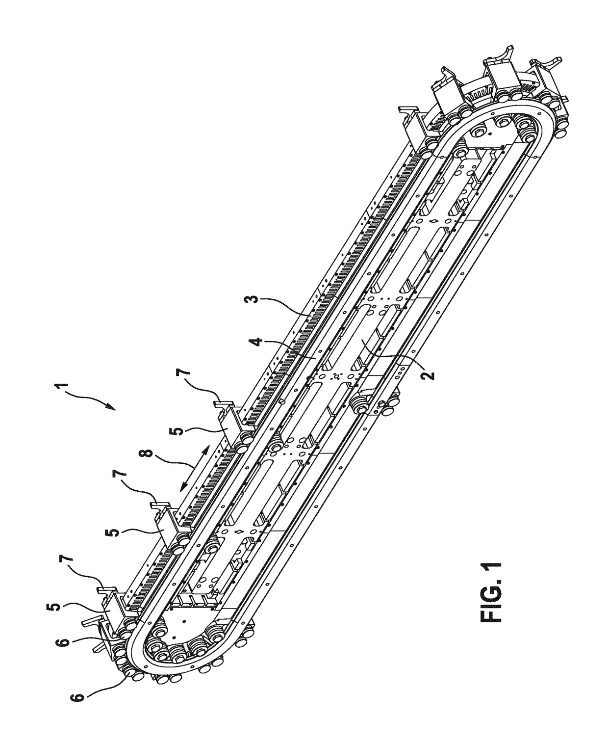
[0033]A first exemplary embodiment is described below with the aid of FIGS. 1 to 6. FIG. 7 shows a second exemplary embodiment, and FIG. 8 shows a third exemplary embodiment. Identical or, respectively, functionally identical components are provided with the same reference signs in all of the examples.

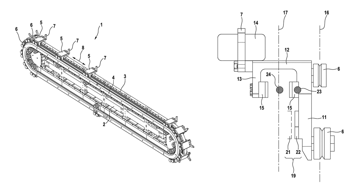
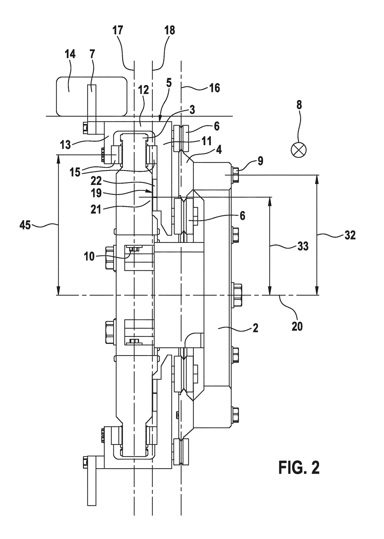
[0034]FIG. 1 shows the transporting arrangement 1 in an isometric view. FIG. 2 shows a sectional view. The transporting arrangement 1 comprises a carrier 2. A stator unit 4 and a guide rail 4 are mounted on this carrier 2. The guide rail 4 is attached by means of a first screw connection 9 to the carrier 2. The stator unit 3 is attached by means of a second screw connection 10 to the carrier 2.

[0035]The stator unit 3 and the guide rail 4 define an annular, continuously rotating movement track for a plurality of transporting units 5. Each transporting unit 5 comprises three supporting elements 6 designed as rollers. These supporting elements 6 are guided on the guide rail 4. As a result...


PUM


Abstract

A transporting arrangement (1) includes at least one guide system having a fixed guide rail (4) and supporting elements (6) which are guided on the guide rail (4), in particular ones designed in the form of rollers and / or sliders, also comprising at least one transporting unit (5), which can be moved in a movement direction (8) and on which the supporting elements are fastened, wherein the transporting unit (5) is guided on the guide rail (4) by the supporting elements (6), and further comprising a linear motor drive arrangement having a fixed stator unit (3) and at least one magnetic element (15), in particular a permanent magnet, on the transporting unit (5), wherein a vertical guide plane (16) is defined, this running parallel to the movement direction (8) and through the center of the guide system, wherein a vertical motor plane (17) is defined, this running parallel to the movement direction (8) and through the center of the linear motor drive arrangement, and wherein a basic body (11) of the transporting unit (5) is arranged between the guide plane (16) and the motor plane (17).

Description

BACKGROUND OF THE INVENTION[0001]The present invention relates to a transporting arrangement for moving products. The transporting arrangement is used especially to transport products and / or containers in filling or packaging plants.[0002]Linear, rotary or integrated transporting arrangements are known in which the transporting units (also: movers) are mounted on a linear, rotary or integrated guide system. The guide rails of the guide system thereby form a path of movement, on which a plurality of individual transporting units are freely movable. The transporting units can be moved via electromagnetic linear drives. By means of these transporting units, products in various formats can be transported individually and independently of one another. U.S. Pat. No. 6,876,107B2 constitutes exemplary prior art.SUMMARY OF THE INVENTION[0003]The transporting arrangement according to the invention ensures a very low-maintenance and reliable operation while at the same time being cost effectiv...

Claims


Application Information

Patent Timeline
Patent Type & Authority Patents(United States)
IPC IPC(8): B65G54/02H02K41/02
CPCH02K41/02B65G54/02
Inventor HANISCH, MARKUSWIPF, ALFREDWANNER, HANSRUEDIKATHAN, PHILIPPSCHWARZ, DANIEL
Owner SYNTEGON TECHNOLOGY GMBH
Why Eureka
Try Eureka