Mandrel

a mandrel and mandrel technology, applied in the field of mandrels, to achieve the effect of reducing the misalignment of the central axes, improving the degree of contact, and keeping the shape of the mandrel

Active Publication Date: 2018-01-09
MITSUBISHI AIRCRAFT
View PDF6 Cites 0 Cited by
  • Summary
  • Abstract
  • Description
  • Claims
  • Application Information

AI Technical Summary

Benefits of technology

[0015]According to the mandrel according to the first aspect of the invention, the mandrel including the core member and the front end member is configured such that the front end member is not mounted on the core member by press fitting, screw fastening, or the like, but the front end member is formed integrally with the core member so as to cover the small-diameter portion of the core member. This improves the degree of closeness of contact between the core member and the front end member, and makes it possible to keep the shape of the mandrel. In addition, since the front end member is not mounted on the core member by press fitting, screw fastening, or the like, but the front end member is formed integrally with the core member, it is possible to reduce the misalignment of the central axes of the core member and the front end member, and this makes it possible to keep the shape of the mandrel.
[0016]According to the mandrel according to the second aspect of the invention, a front end member made of a resin is formed by injection molding. This makes it possible to surely form the front end member on the core member in a close contact state. In addition, the resin member improves the slidability between the mandrel and a pipe material to be bent. Hence, no lubricant oil is used at the bending of a pipe material, which makes it possible to eliminate the need for the washing operation for removing lubricant oil.
[0017]According to the mandrel according to the third aspect of the invention, a front end member made of a ceramic is formed by sintering. This makes it possible to surely form the front end member on the core member in a close contact state. In addition, the ceramic member improves the slidability between the mandrel and a pipe material to be bent. Hence, no lubricant oil is used at the bending of a pipe material, which makes it possible to eliminate the need for the washing operation for removing lubricant oil.
[0018]According to the mandrel according to the fourth aspect of the invention, the groove portion is provided in the small-diameter portion of the core member, and hence the front end member is formed, while entering the groove portion. Hence, the groove portion acts as a retainer. In other words, when a force acts on the core member in the mandrel in a direction to release the front end member, the front end member is caught by the groove portion in the core member, and does not come off from the core member.

Problems solved by technology

However, since the lubricant oil is attached to the inner surface of the pipe, the bending using lubricant oil requires a washing operation for removing the lubricant oil by washing the inside of the pipe after the bending.

Method used


Image

  • Mandrel
  • Mandrel
  • Mandrel

Examples


first embodiment

[0024]{First Embodiment}

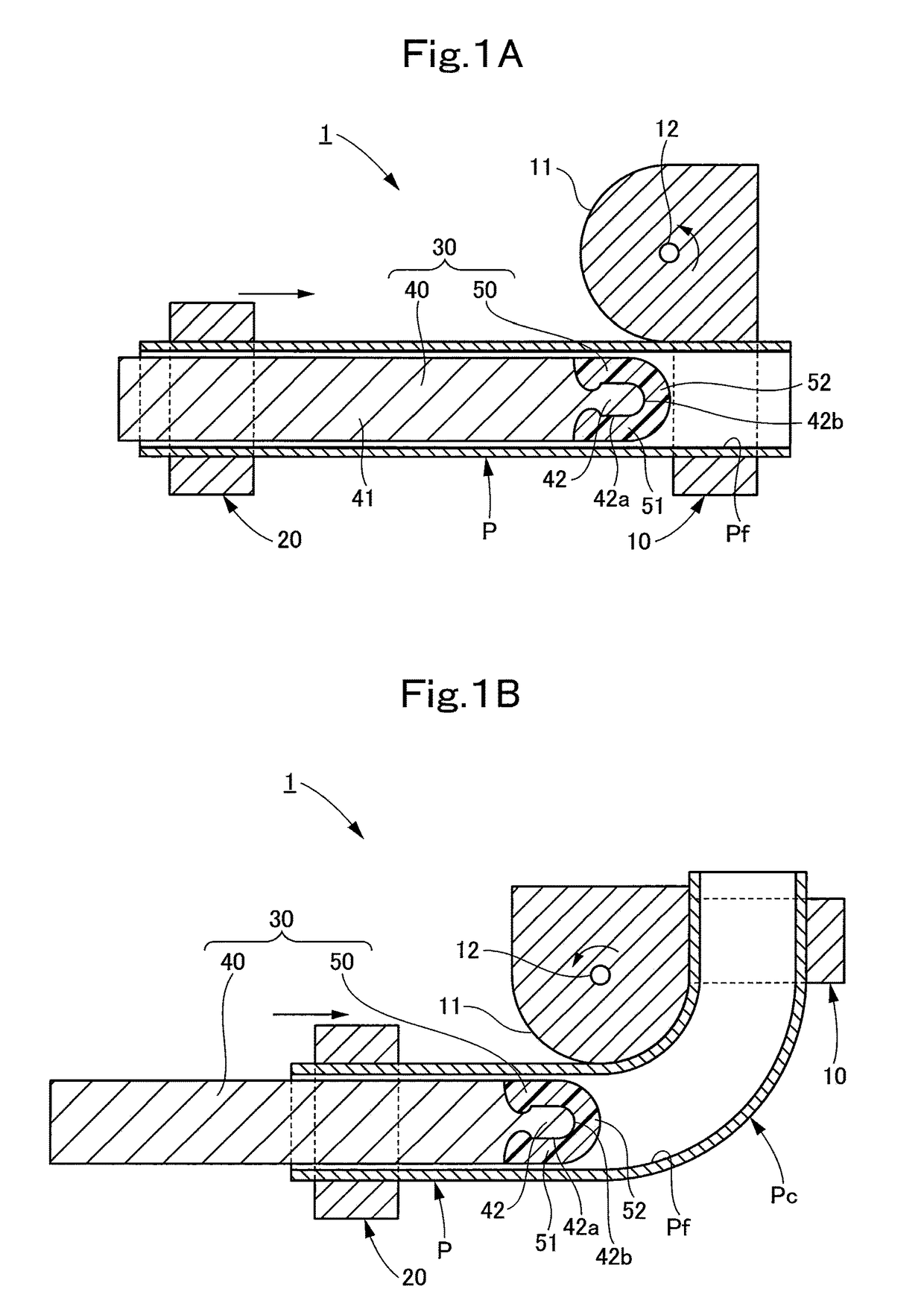
[0025]A structure of a bending machine equipped with a mandrel according to a first embodiment of the present invention is described with reference to FIGS. 1A and 1B and FIG. 2.

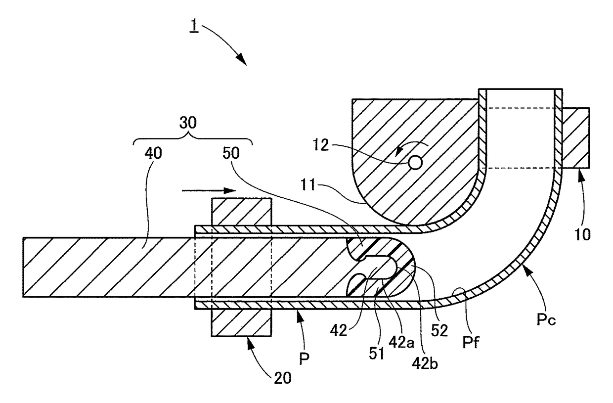
[0026]As shown in FIG. 1A, a bending machine 1 includes a first supporting portion 10 configured to support a part of a pipe (pipe material) P on a front end side of the pipe P (on the right side in FIG. 1A), and a second supporting portion 20 configured to support a part of the pipe P on a rear end side of the pipe P (on the left side in FIG. 1A).

[0027]The first supporting portion 10 has a guide face 11 having an arc shape with a predetermined curvature. The first supporting portion 10 is rotatable about a rotation axis 12 positioned at a center of the arc of the guide face 11. On the other hand, the second supporting portion 20 is configured to linearly move with the rotation of the first supporting portion 10 to push the pipe P toward the front end (in a direction of a tangent to t...

second embodiment

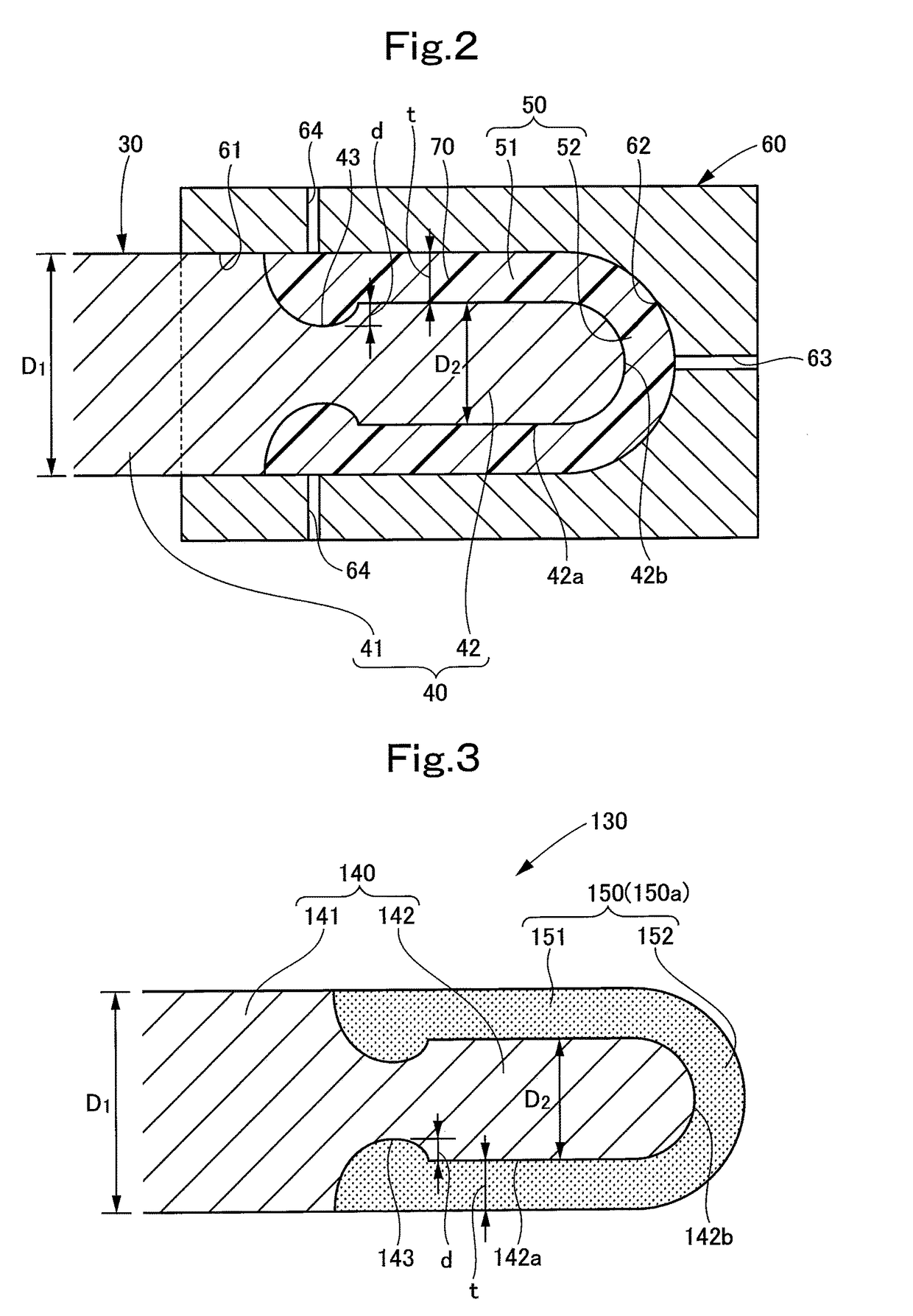
[0048]{Second Embodiment}

[0049]A structure of a bending machine equipped with a mandrel according to a second embodiment of the present invention is described with reference to FIGS. 1A and 1B and FIG. 3.

[0050]A mandrel 130 according to this embodiment is provided instead of the mandrel 30 in the bending machine 1 in the first embodiment of the present invention (see FIGS. 1A and 1B). Specifically, the bending machine equipped with the mandrel 130 according to this embodiment has the same structure as that of the bending machine 1 equipped with the mandrel 30 according to the first embodiment of the present invention, except for the structure of the mandrel 130, specifically, except that a front end member 150 of the mandrel 130 is made of a ceramic instead of the resin. Accordingly, overlapping descriptions for similar structures in the bending machine equipped with the mandrel 130 according to this embodiment to those in the first embodiment are omitted, as appropriate.

[0051]The m...


PUM

PropertyMeasurementUnit
angleaaaaaaaaaa
diameteraaaaaaaaaa
timeaaaaaaaaaa

Abstract

Provided is a mandrel which is inserted into a pipe material when the pipe material is bent, the mandrel including: a core member having a rod-shaped main body portion and a small-diameter portion which is provided on one end side of the main body portion and which is thinner than the main body portion; and a front end member which is provided on one end side of the core member and which is formed integrally with the core member so as to cover the small-diameter portion.

Description

TECHNICAL FIELD[0001]The present invention relates to a mandrel which is inserted into a pipe material when the pipe material is bent.BACKGROUND ART[0002]As a bending machine for bending a pipe (pipe material) to a predetermined curvature, for example, a bending machine is known which includes a first supporting portion configured to support a part of a pipe on one end side thereof and a second supporting portion configured to support a part of the pipe on the other end side thereof, and which is configured to bend the pipe along an arc-shaped guide face provided on the first supporting portion by rotating the first supporting portion about a predetermined rotation axis and also causing the second supporting portion to linearly move.[0003]Such a bending machine is equipped with a mandrel for preventing the deformation (flattening) of a pipe at bending, and a pipe is bent with the mandrel inserted in the pipe.[0004]In the bending of a pipe using a mandrel, lubricant oil is used in so...

Claims


Application Information

Patent Timeline
Patent Type & Authority Patents(United States)
IPC IPC(8): B21B19/04B21B25/00B21D37/01B21D9/07
CPCB21D9/073B21D37/01B21B25/00B21B19/04
Inventor KAWAMOTO, HIROSHIYASUI, TOYOAKIKUROI, KUNIHIROKISHIDA, TOMONE
Owner MITSUBISHI AIRCRAFT
Why Eureka
Try Eureka