Optical element, lighting device and luminaire

a technology of optical elements and lighting devices, applied in semiconductor devices, lighting and heating apparatus, instruments, etc., can solve the problems of dissuading consumers from purchasing ssl element-based lighting devices, affecting the penetration of ssl elements in the market, and affecting the degree of scattering, etc., to achieve a high degree of flexibility, easy to vary, and increase the effect of scattering

Active Publication Date: 2018-01-16
SIGNIFY HLDG BV
View PDF13 Cites 0 Cited by
  • Summary
  • Abstract
  • Description
  • Claims
  • Application Information

AI Technical Summary

Benefits of technology

[0015]Such an optical element can be used in conjunction with an annular pattern of solid state lighting elements wherein the elements are arranged such that the luminous output is coupled into the optical element adjacent to the first aperture. The combined continuous inner surfaces combine to form a (approximated) curved inner surface that reflects part of the luminous output of the solid state lighting elements whilst allowing another part of the luminous output to travel through the curved inner surface into the cavity of the optical element. This ensures that the light generated by the SSL elements is scattered in a large number of directions, which can be used to create an appearance of omnidirectional luminance and / or a sparkling effect. At the same time, the number of SSL elements in the annular pattern can be easily varied, as this does not affect the performance of the optical element. As such, the optical element provides a high degree of flexibility as it can be used with a wide variety of annular SSL element patterns.
[0016]In an embodiment, each prismatic surface has a reflective second surface portion, wherein the first surface portion tapers from the second surface portion in the direction of the first aperture. This further increases the degree of scattering produced by the optical element, thereby further improving the approximation of omnidirectional luminance produced by a lighting device comprising the optical element.
[0025]According to another aspect, there is provided a lighting device comprising a plurality of solid state lighting elements in a circular pattern and the optical element according to an embodiment of the present invention, wherein the first frustum is placed over the solid state elements such that the solid state lighting elements are arranged to emit light into the first frustum. This provides a lighting device that closely mimics the luminous distribution of an incandescent counterpart and that can be manufactured in a cost-effective manner due to the reusability of the optical element therein.

Problems solved by technology

However, market penetration of SSL elements is hampered by a number of factors.
Secondly, the manufacturing cost of SSL element-based lighting devices is significantly higher than the manufacturing cost of incandescent lighting devices.
Although this higher cost is offset by the superior lifetime of the SSL element-based lighting devices, it nevertheless dissuades consumers from purchasing SSL element-based lighting devices as the initial cost may be considered prohibitive.
The above problems pose a fundamental dilemma for the manufacturers of SSL element-based lighting devices, because in order to more closely match the appearance of incandescent counterparts additional optical elements have to be added to the design of the lighting device.
However, such additional optical elements can significantly add to the cost of the SSL element-based lighting device.
This problem is particularly relevant when the lighting device is a light bulb, especially light bulbs that are expected to have a traditional appearance such as candle-shaped light bulbs
Although this optical element ensures that the luminous distribution closely mimicking that of an incandescent light bulb is achieved, e.g. it can closely mimic the sparkling effect of an incandescent candle light bulb, a drawback is that the design of the optical element is closely linked to the number of light-emitting diodes in the lighting device where the optical element is to be used.
The limited reusability of such optical elements is a contributing factor in the relatively high cost of SSL element-based lighting devices.

Method used


Image

  • Optical element, lighting device and luminaire
  • Optical element, lighting device and luminaire
  • Optical element, lighting device and luminaire

Examples


Embodiment Construction

It should be understood that the FIG.s are merely schematic and are not drawn to scale. It should also be understood that the same reference numerals are used throughout the FIG.s to indicate the same or similar parts.

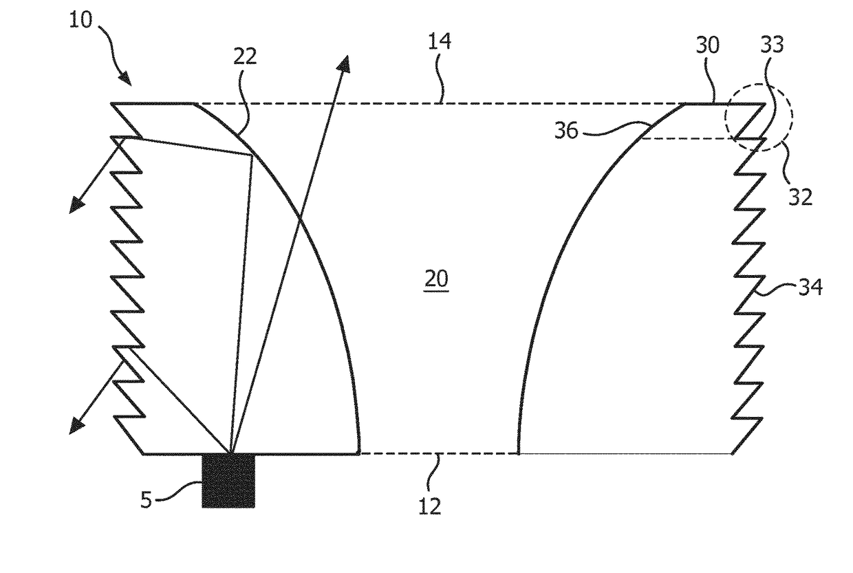
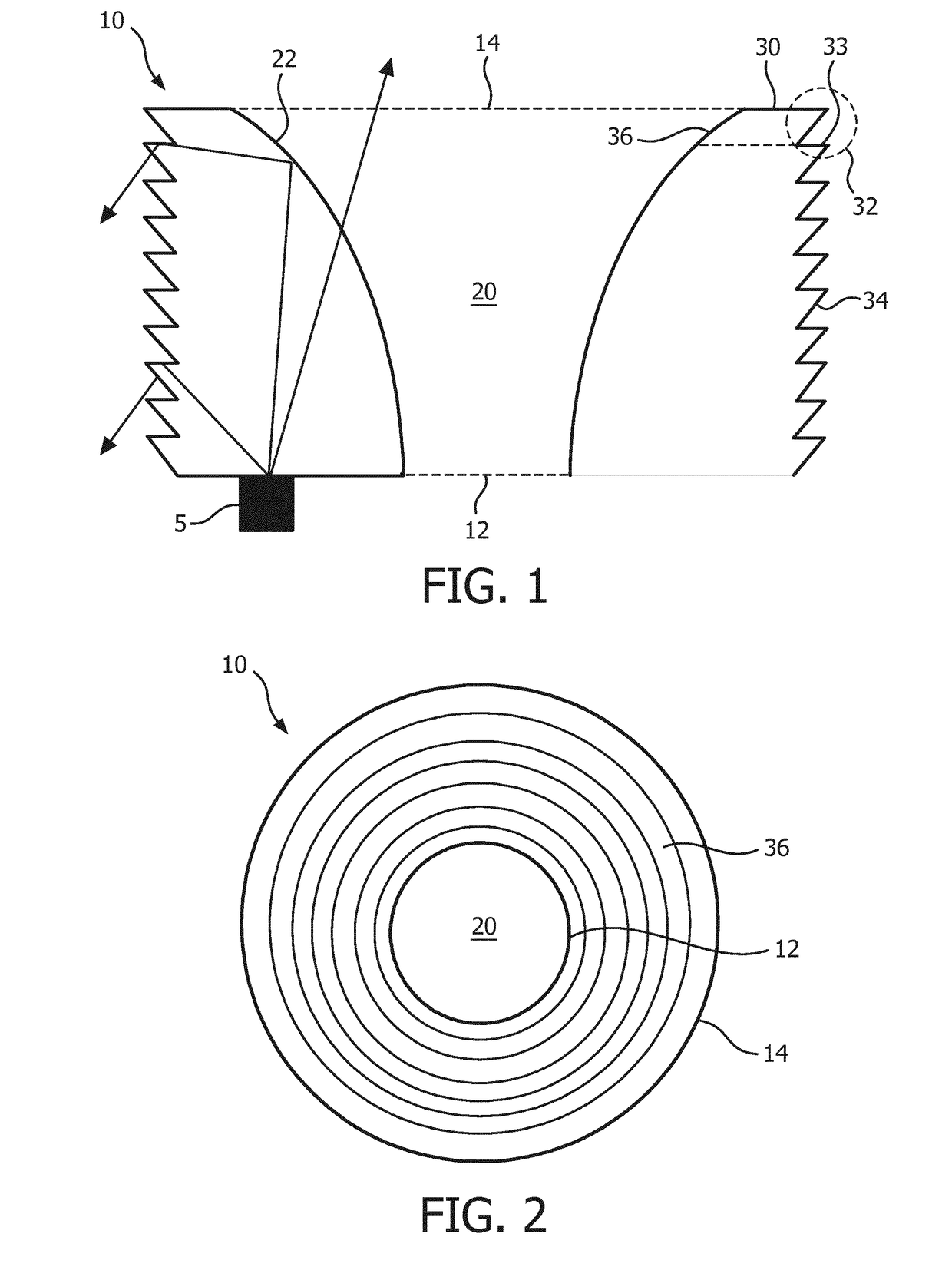
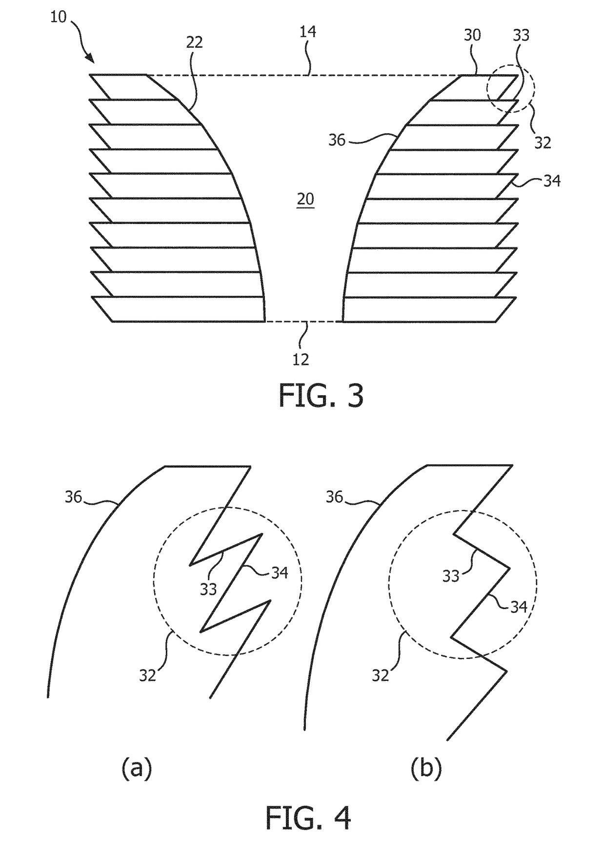
[0037]FIG. 1 schematically depicts a cross-section of an optical device 10 in accordance with an embodiment of the present invention, and FIG. 2 schematically depicts a top view of the optical device 10. The optical device 10 has a main body formed by a plurality of frustums 30. Each frustum 30 has an inner surface 36, wherein the inner surfaces 36 of the frustums 30 combine to delimit an inner cavity 20 of the optical element 10. The frustums 30 are shaped such that the cavity 20 tapers from a second aperture 14 towards a first aperture 12. In other words, the cavity 20 gradually widens in the direction from the first aperture 12 to the second aperture 14. The inner surfaces 36 of the frustums 30 may be curved surfaces such that the inner surface 22 of the optical ele...


PUM

PropertyMeasurementUnit
transparentaaaaaaaaaa
widthaaaaaaaaaa
total internal reflectionaaaaaaaaaa

Abstract

Disclosed is an optical element (10) comprising a central cavity (20) extending from a first aperture (12) to a second aperture (14) of the optical element, said central cavity gradually widening in a direction from the first aperture to the second aperture, said central cavity being delimited by a stack of transparent frustums (30) including a first frustum defining the first aperture and a final frustum defining the second aperture, each frustum having a prismatic outer surface (32) having a first surface portion (34) tapering in the direction from the second aperture to the first aperture and a continuous inner surface (36), wherein the respective continuous inner surfaces combine to delimit said central cavity. Also disclosed is a lighting device including such an optical element and a luminaire including such a lighting device.

Description

CROSS-REFERENCE TO PRIOR APPLICATIONS[0001]This application is the U.S. National Phase application under 35 U.S.C. §371 of International Application No. PCT / EP2014 / 079325, filed on Dec. 24, 2014, which claims the benefit of European Patent Application No. 14163375.0, filed on Apr. 3, 2014, and International Patent Application No. PCT / CN2014 / 070064. These applications are hereby incorporated by reference herein.FIELD OF THE INVENTION[0002]The present invention relates to an optical element for use in a lighting device such as a light bulb.[0003]The present invention further relates to a lighting device including such an optical element.[0004]The present invention yet further relates to a luminaire including such a lighting device.BACKGROUND OF THE INVENTION[0005]Solid state lighting (SSL) elements such as LEDs are rapidly gaining popularity as the successor of more energy-inefficient lighting devices such as incandescent lighting devices. However, market penetration of SSL elements i...

Claims


Application Information

Patent Timeline
Patent Type & Authority Patents(United States)
IPC IPC(8): F21V5/02F21V7/00F21K9/232F21V3/02G02B19/00F21K9/60F21V13/04F21V3/04F21W121/00F21Y115/10
CPCF21V5/02F21K9/232F21K9/60F21V3/02F21V7/0091G02B19/0061G02B19/0071F21V13/04F21Y2115/10F21V3/0427F21V3/0445F21W2121/00F21V3/0615F21V3/0625G02B19/0066G02B19/0028F21V5/00
Inventor SHEN, MOLI, YUN
Owner SIGNIFY HLDG BV
Why Eureka
Try Eureka