Minimal contact splinting for mallet finger deformity

a technology of mallet finger and splinting, which is applied in the field of treating, nonsurgically, with splinting, a mallet finger deformity, can solve the problems of difficult to fully straighten the finger, difficult to disassemble the finger, and the tip of the finger to droop, so as to avoid skin maceration and ulceration, and easy disassembly and re-assembly

Inactive Publication Date: 2018-01-23
KARNA RATISH K
View PDF6 Cites 5 Cited by
  • Summary
  • Abstract
  • Description
  • Claims
  • Application Information

AI Technical Summary

Benefits of technology

[0007]The present invention overcomes the aforementioned deficiencies and the problems that remain unsolved by providing an apparatus, method and system for treating the mallet finger deformity (referred to hereinafter as a flexion deformity) by splinting the DIP joint in a neutral or slight hyperextension position with minimal skin contact. So the splinting technique of the present invention is based on the concept of minimum skin contact (referred to hereinafter as Minimal Contact Splinting or MCS) with the involved body part. The material used by the splinting...

Problems solved by technology

In other words, it is a condition of a finger where the tendon in the outermost joint of the finger is ruptured, principally due to jamming of the finger at its outer tip, causing the tip of the finger to droop and thereafter making it difficult to fully straighten the finger.
Both the existing splinting techniques often result in skin maceration, ulceration, and foul smell due to moisture deposition within the splint, and also restrict patients from getting the finger wet.
This involves the risk of accidental loss of positioning maintained by the splint.
The pre-fabricated splint comes in different sizes yet often finding the correct ...

Method used


Image

  • Minimal contact splinting for mallet finger deformity
  • Minimal contact splinting for mallet finger deformity
  • Minimal contact splinting for mallet finger deformity

Examples


Embodiment Construction

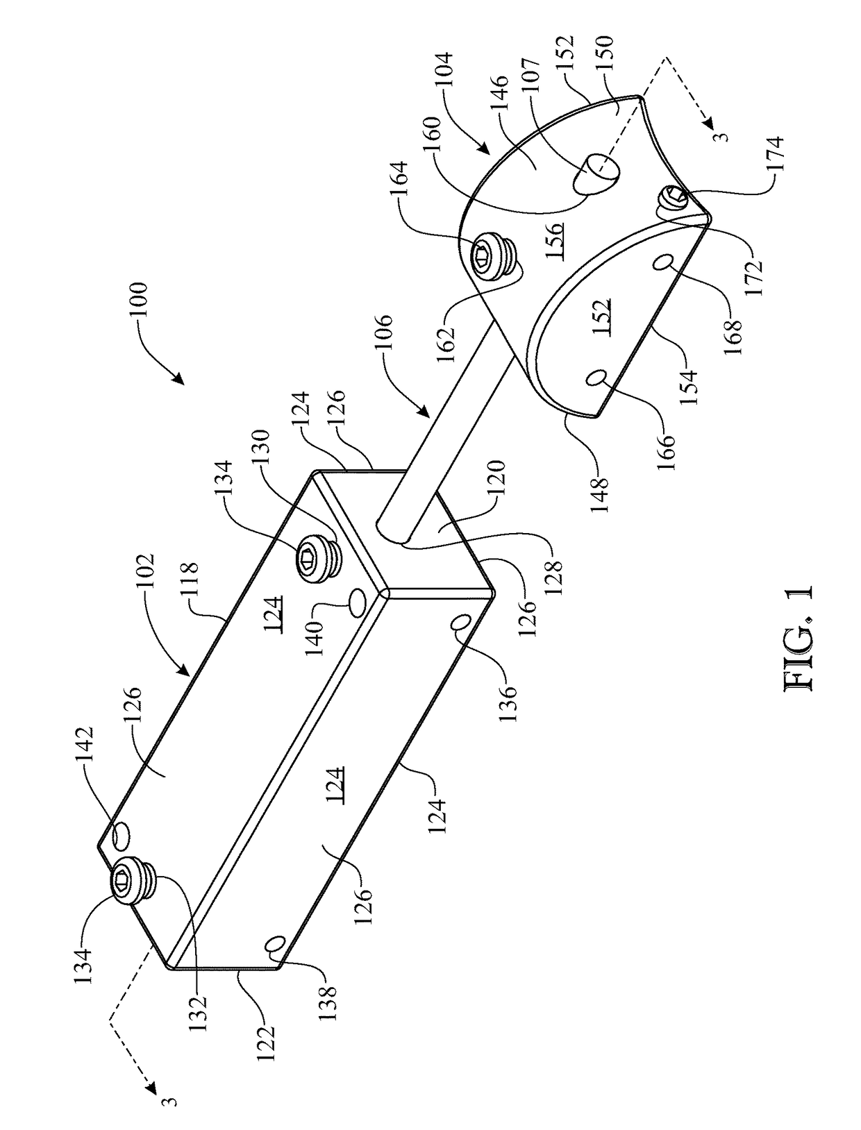
[0051]The following detailed description is merely exemplary in nature and is not intended to limit the described embodiments or the application and uses of the described embodiments. As used herein, the word “exemplary” or “illustrative” means “serving as an example, instance, or illustration.” Any implementation described herein as “exemplary” or “illustrative” is not necessarily to be construed as preferred or advantageous over other implementations. All of the implementations described below are exemplary implementations provided to enable persons skilled in the art to make or use the embodiments of the disclosure and are not intended to limit the scope of the disclosure, which is defined by the claims. For purposes of description herein, the terms “upper”, “lower”, “left”, “rear”, “right”, “front”, “vertical”, “horizontal”, and derivatives thereof shall relate to the invention as oriented in FIG. 1. Furthermore, there is no intention to be bound by any expressed or implied theo...


PUM


Abstract

A splinting apparatus treating a flexion deformity of a finger includes a phalangeal bracket and a first anchoring ring fixedly attached thereto and positioned on the finger proximally of the deformity, a nail bracket and a second anchoring ring fixedly attached thereto and positioned on the finger distally of the deformity, and a rigid connecting rod extending between, and fixedly attached to at least one of the phalangeal and nail brackets so as to couple the brackets in a spaced apart positional relationship to each other along the finger relative to the flexion deformity. Each of the first and second anchoring rings is formed from an elongated narrow band integrally connected respectively with one of the phalangael and nail brackets and having first and second band extensions being bendable in opposite directions circumferentially around the finger so as to overlap and secure to one another.

Description

CROSS REFERENCE TO RELATED APPLICATION[0001]This non-provisional patent application is a continuation-in-part of co-pending U.S. non-provisional utility patent application Ser. No. 14 / 048,275 filed on Oct. 8, 2013, which is hereby incorporated-by-reference herein in its entirety.FIELD OF THE INVENTION[0002]The present invention relates to treating, non-surgically by splinting, a mallet finger deformity, and more particularly, is concerned with an apparatus, method and system for treating the finger by splinting with minimal skin contact the distal interphalangeal (DIP) joint in a neutral or slight hyperextension position.BACKGROUND OF THE INVENTION[0003]A mallet finger deformity of a finger occurs due to rupture or avulsion of Extensor Digitorum Communis (EDC) tendon at its insertion on the distal phalanx. In other words, it is a condition of a finger where the tendon in the outermost joint of the finger is ruptured, principally due to jamming of the finger at its outer tip, causing...

Claims


Application Information

Patent Timeline
IPC IPC(8): A61F5/05A61F5/058
CPCA61F5/05875A61F5/10
Inventor KARNA, RATISH K.
Owner KARNA RATISH K
Why Eureka
Try Eureka