Foot implant for bone fixation

a technology for implants and bones, applied in the field of human bones implanted in the foot, can solve the problem of not accepting a plate for covering the bone screws

Active Publication Date: 2018-01-30
LIFE SPINE INC
View PDF173 Cites 6 Cited by
  • Summary
  • Abstract
  • Description
  • Claims
  • Application Information

AI Technical Summary

Benefits of technology

[0008]The present invention is a wedge-shaped bone implant, system and method of use, particularly but not necessarily, for fixing bones of the foot. The wedge-shaped bone implant has bone screw bores that are each configured to hold a bone screw at a particular angle for receipt in a foot bone portion, thereby eliminating the need to also use a plate.
[0009]In one form, the wedge-shaped bone implant is moreover configured to receive a plate that aids in preventing a bone screw from backing out of its implant bore. The plate may be fastened to the wedge-shaped bone implant by one or more fastening screws. In this form, the top of the wedge-shaped implant has a recess that at least partially surrounds openings of the two implant bores. The recess is configured to receive the plate such that the plate at least partially obstructs the ability of a bone screw head within the implant bore to back out. Moreover, in this form, one or more of the threaded fastening screw bores for the fastening screws of the cover, may be used for engagement with an insertion instrument.
[0015]According to one method of use, the foot bone implant is placed into a foot bone joint to correct a deformity and provide fixation for fusion. The present foot bone implant permits the inclusion of bone screws to self-retain the wedge within the joint as well as providing stability for fusion. This is accomplished without the need for an additional plate.
[0016]According to another method of use, bone graft material is placed in the graft window of the foot bone implant. The foot bone implant with bone graft material is then placed into a foot bone joint, foot bone osteotomy site, foot bone fracture or the like and provide fixation for fusion. The foot bone implant with bone graft material permits the inclusion of bone screws to self-retain the wedge within the joint as well as providing stability for fusion. Again, this is accomplished without the need for an additional plate.

Problems solved by technology

In another form, the wedge-shaped bone implant lacks a configuration on the top and thus does not accept a plate for covering the bone screws.

Method used


Image

  • Foot implant for bone fixation
  • Foot implant for bone fixation
  • Foot implant for bone fixation

Examples


Embodiment Construction

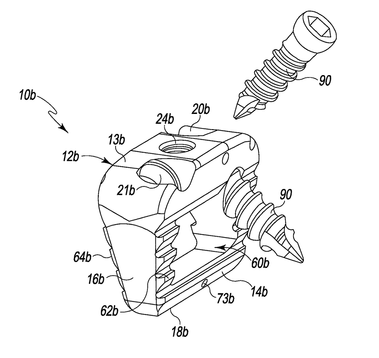
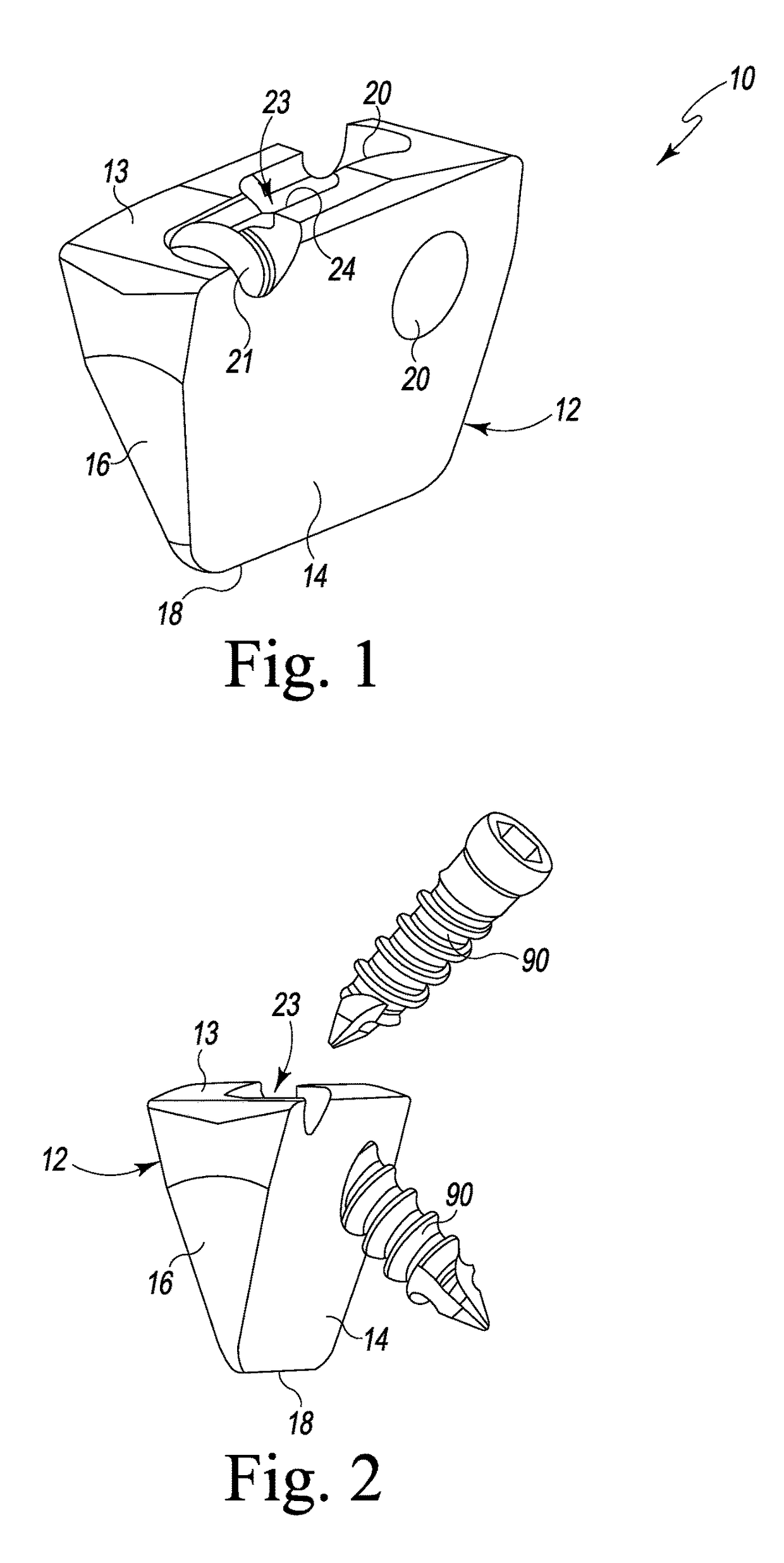
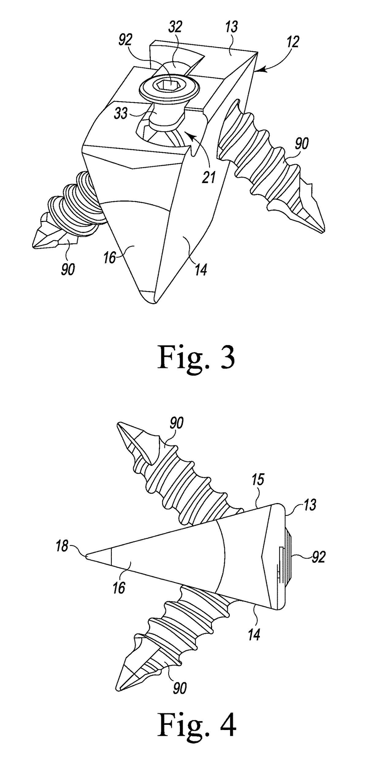
[0034]Referring to FIGS. 1-6 and, in particular FIG. 1, there is depicted a foot bone implant generally designated 10. The foot bone implant 10 is fashioned from a known biocompatible implant material and is used for aiding or providing internal fixation of calcaneus, tarsal, and metatarsal bones of the foot in cases such as, but not limited to, filling an osteotomy or expanding and correcting an angular deformity in the foot. Other uses are contemplated. The foot bone implant 10 has a generally wedge-shaped body 12 as wedges are defined in solid geometry and explained in the Summary of the Invention. As such, the body 12 has a generally rounded top 13, a generally planar first side 14, a generally planar second side 15 (see FIG. 4), a generally planar first end 16, a generally planar second end 17 (see FIG. 4), and a generally pointed bottom 18. The first and second sides 14 and 15 each slope inwardly from the top 13 to the bottom 18. The dimensions and angles of the foot bone impl...


PUM


Abstract

A wedge-shaped bone implant, particularly but not necessarily, for fixing bones of the foot is provided. The implant has bone screw bores that are each configured to hold a bone screw at a particular angle for receipt in a foot bone, eliminating the need to also use a plate. The implant can include an opening that extends through the implant body from one tapered side thereof to the other tapered side thereof. This opening allows the introduction and retention of bone graft material to promote bone fusion. One or both tapered sides of the body may also have teeth, serrations or the like. The implant body may include a hole or the like in the distal aspect thereof. This allows for the insertion of a metallic component (e.g. titanium or tantalum) to allow for the visibility of the extent of the implant body in radiography, x-ray, or the like.

Description

CROSS-REFERENCE TO RELATED APPLICATIONS[0001]This U.S. non-provisional patent application claims the benefit of and / or priority under 35 U.S.C. § 119(e) to U.S. provisional patent application Ser. No. 61 / 936,644 filed Feb. 6, 2014 titled “Foot Implant For Bone Fixation,” the entire contents of which is specifically incorporated herein by reference.BACKGROUND OF THE INVENTION[0002]Field of the Invention[0003]The present invention relates to implants for fixation of human bones, and particularly, to implants for fixation of bones of the foot. More particularly, the present invention relates to implants for internal fixation of calcaneus, tarsal, and metatarsal bones of the foot.[0004]Background Information[0005]There are many reasons why surgeries are performed on the bones of the foot. Some foot surgeries such as osteotomies are performed to correct angular deformities. Other foot surgeries are performed to mend a fracture or to re-align or reposition bones of the foot. In these surg...

Claims


Application Information

Patent Timeline
Patent Type & Authority Patents(United States)
IPC IPC(8): A61B17/80
CPCA61B17/8095A61B17/8061A61B17/8042
Inventor PREDICK, DANIEL
Owner LIFE SPINE INC
Why Eureka
Try Eureka