Overhead luggage compartment for aircraft

Active Publication Date: 2018-01-30
FACC
View PDF39 Cites 8 Cited by
  • Summary
  • Abstract
  • Description
  • Claims
  • Application Information

AI Technical Summary

Benefits of technology

The present invention aims to create an overhead bin for airplanes that has a large luggage-receiving space while being lightweight and easy to manufacture. Additionally, the invention seeks to provide an airplane with one aisle that can be equipped with different overhead bins quickly and easily. These bins should be easy to load and unload while restricting the moving space of passengers as little as possible.

Problems solved by technology

Such an overhead bin, which may be designed as both a fixed bin and a movable bin, permits receiving most pieces of cabin luggage in an endwise horizontal or vertical position, which has not been possible with previous bins.

Method used


Image

  • Overhead luggage compartment for aircraft
  • Overhead luggage compartment for aircraft
  • Overhead luggage compartment for aircraft

Examples


Embodiment Construction

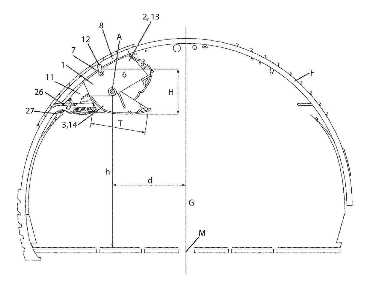
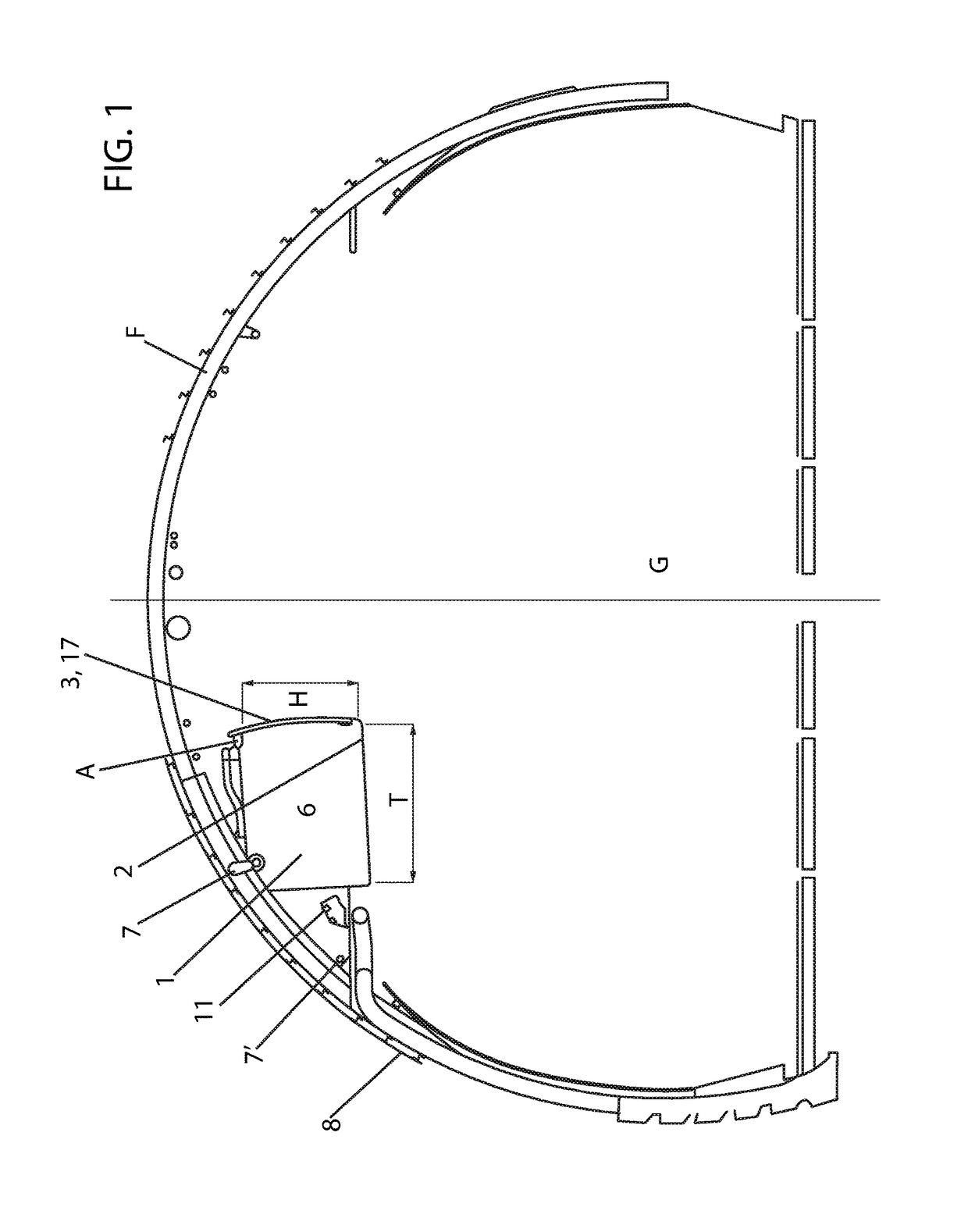
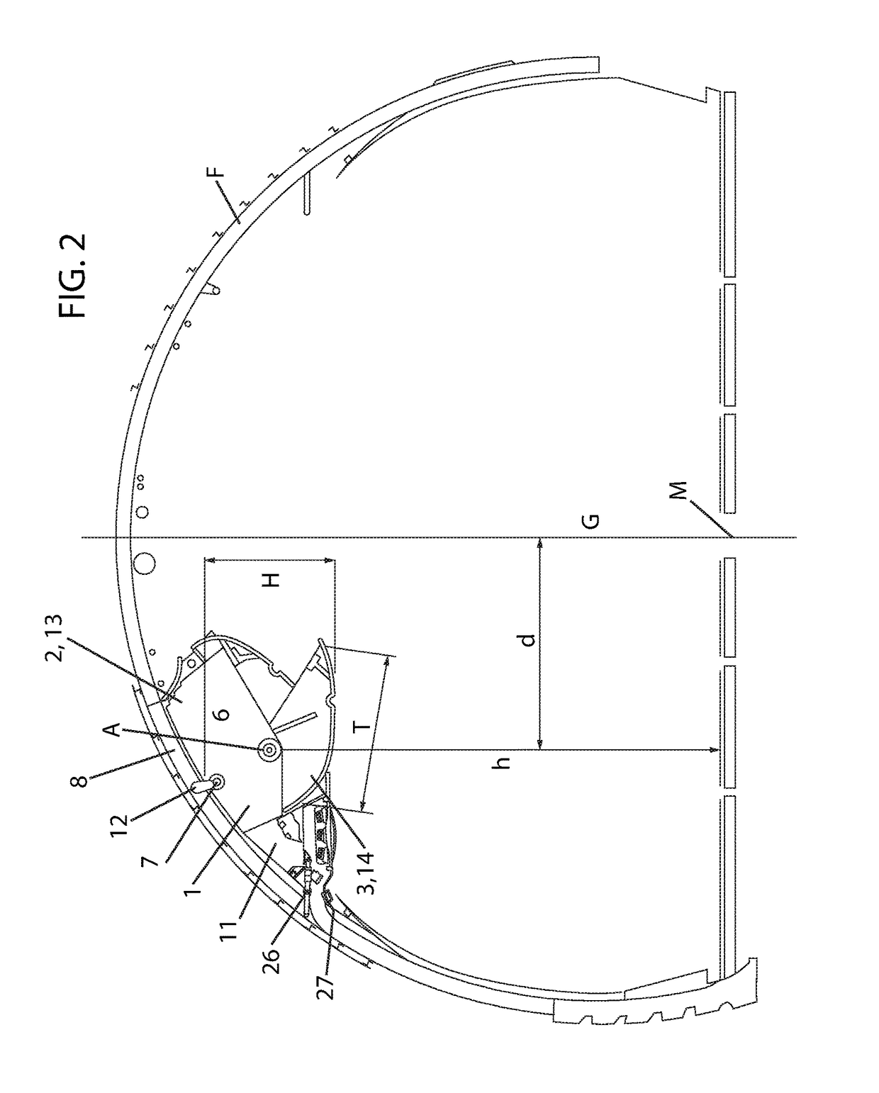
[0049]FIG. 1 illustrates schematically a part of a fuselage of an airplane F having one aisle G and overhead bins 1 arranged on the left-hand side of the aisle G. Typically, like overhead bins 1 are arranged on the right-hand side of the aisle G as well, but they are omitted here for the sake of simplicity. The overhead bins 1 comprise a stationary part 2 having side walls 4 (see FIG. 5) and a movable part 3 which is designed pivotable around a rotation axis A. In the illustrated example the overhead bins 1 are so-called fixed or stationary overhead bins 1, in which the stationary part 2 is substantially designed in the shape of a cuboid having an open front side and the movable part 3 is designed as a flap 17. The flap 17 is pivotable around a rotation axis A arranged on the top edge of the open front side of the cuboid-shaped stationary part 2. The overhead bin 1 is fastened to the supporting structure 8 of the airplane F by appropriate fastening devices 7, 7′. For absorbing force...


PUM


Abstract

An overhead luggage compartment for aircraft can be constructed as a fixed luggage compartment with a stationary housing and a pivotable flap, or as a lowerable luggage compartment with a lowerable tray, a stationary part having side walls and a movable part which is pivotable between a closed and an open position and has a closure element for retaining the movable part in the closed position. Those parts define a luggage-receiving space. Two fastening devices for fastening to a supporting structure of the aircraft on the side walls of the stationary part are disposed on the stationary part. At least one further fastening device is disposed in the region of the lower side of the rear side of the stationary part. The fastening devices are the same for the fixed luggage compartment and for the lowerable luggage compartment.

Description

BACKGROUND OF THE INVENTIONField of the Invention[0001]The invention relates to an overhead luggage compartment for airplanes, which can be designed as a fixed bin with a stationary housing and a pivotable flap, or as a movable bin with a lowerable tray, with a stationary part having side walls and with a movable part which is pivotable between a closed and an open position around a rotation axis, and with a closure element for retaining the movable part in the closed position, said parts defining a luggage-receiving space, wherein fastening devices for fastening to a supporting structure of the airplane are arranged on the stationary part, and at least one suspension device for a passenger service unit is arranged.[0002]Furthermore, the invention relates to an airplane having an aisle and overhead bins of the above type arranged on both sides of the aisle.[0003]The present invention relates mainly to luggage bins for passenger planes. However, use for rail vehicles or other means o...

Claims


Application Information

Patent Timeline
IPC IPC(8): B64D11/00
CPCB64D11/003Y02T50/46Y02T50/40B64D11/00
Inventor KAMMERER, BERNHARDSCHOERKHUBER, JAKOB
Owner FACC
Why Eureka
Try Eureka