Unlock instant, AI-driven research and patent intelligence for your innovation.
Systems and methods for assembling aircraft wing skins
What is Al technical title?
Al technical title is built by PatSnap Al team. It summarizes the technical point description of the patent document.
a technology for aircraft wings and wing skins, which is applied in the direction of rivets, wings, securing devices, etc., can solve the problems of increasing process flow time, difficult to maintain the drill bit normal to the surface of the panel, and substantially manual processes involved in the attachment of the panel to the underlying structure with fasteners
Active Publication Date: 2018-01-30
THE BOEING CO
View PDF2 Cites 0 Cited by
Summary
Abstract
Description
Claims
Application Information
AI Technical Summary
This helps you quickly interpret patents by identifying the three key elements:
Problems solved by technology
Method used
Benefits of technology
Benefits of technology
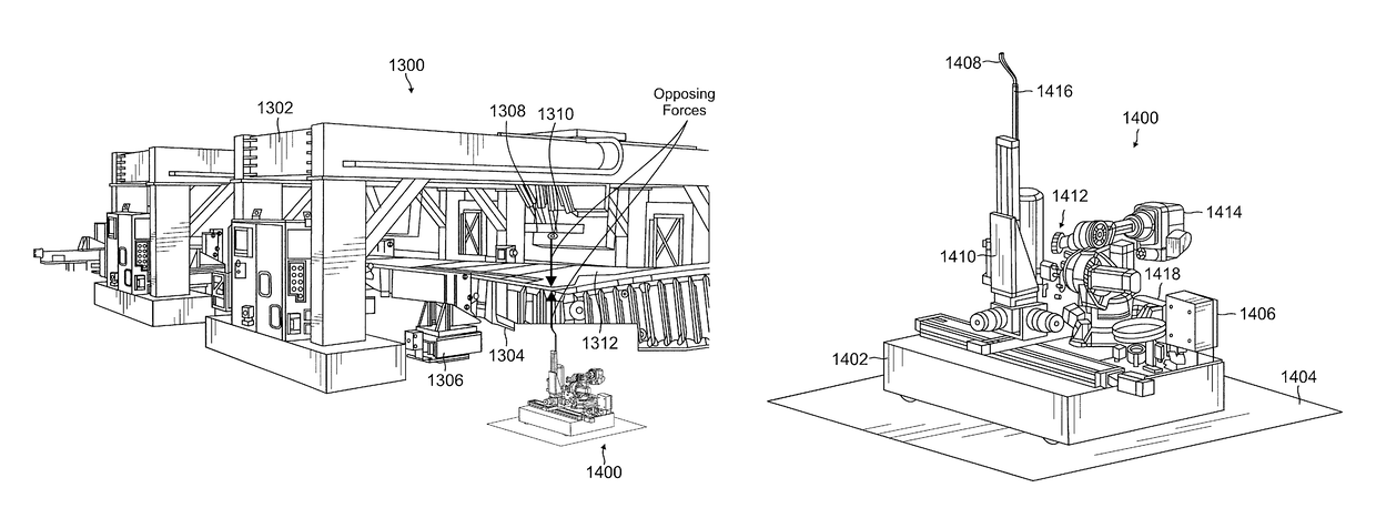
[0007]In accordance with embodiments of the present disclosure, automated systems and methods are provided, including a mobile automated collar installation system, for assembling upper skin panels of aircraft wings to underlying wing support structures that eliminate the drawbacks of the conventional, manually implemented processes.
Problems solved by technology
In either case, however, the processes involved in the attachment of the panels to the underlying structure with fasteners have heretofore been substantially manual in nature.
While the foregoing procedures result in satisfactory wing assemblies, they are not without some drawbacks, primarily relating to the drilling of the fastener holes and the installation of the fastener collars.
It is difficult to maintain the drill bit normal to the surface of the panels manually while drilling quality holes.
Further, since the workers cannot completely close any gaps between the skin panels and the underlying wing structures using only hand drills, this procedure necessitates the added step of separating the skin panels from the underlying structure after drilling to clean the interface between the panel and the underlying wing structure, which is time consuming and adds process flow time, as it is difficult to realign the holes.
Any misalignment usually results in hole damage during insertion of the fastener and a corresponding need for rework.
The process also has relatively high labor content, because the existing collaring process is also effected manually, i.e., a worker must stand or sit on the floor beneath the wing and work overhead to attach each collar using a manually operated swaging tool.
This is fatiguing work that is prone to part damage and worker injuries, and is performed in a separate build position downstream from the drilling and fastener insertion operation to balance work across the line.
Method used
Image
Click on the blue label to locate the original text in one second.
Reading with bidirectional positioning of images and text.
Examples
Embodiment Construction
[0026]In accordance with embodiments of the present disclosure, automated systems and methods are provided, including a robotic mobile automated collar installation system (MACIS), for assembling upper skin panels of aircraft wings to underlying wing support structures with lockbolt-type fasteners.
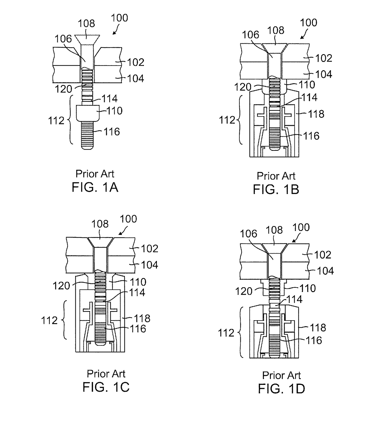
[0027]FIGS. 1A-1D are partial cross-sectional views of a first type of a typical lockbolt fastener 100 currently used to assemble an aircraft skin panel 102 to an underlying wing structure 104 such as a wing rib, spar, shear tie, frame or the like, showing some sequential steps involved in the assembly. In the particular example embodiment of FIGS. 1A-1D, the fastener 100 comprises a HUCK type lockbolt fastener, but as discussed below, other types of lockbolt fasteners are also available and may be used. As can be seen in these figures, the fastener 100 comprises an elongated “pin” or shaft 106, a head 108 disposed concentrically at an upper end of the shaft 106, and a locking nut or “coll...
PUM
Abstract
In one embodiment, a system includes a first end effector configured to press a selected area of an aircraft wing skin panel against a corresponding area of an underlying wing support structure with a downward force, drill a hole within the selected area, the hole extending through the skin panel and the support structure, and insert an elongated shaft of a fastener into the hole. The system includes a mechanism configured to locate the first end effector relative to the selected area. The system can further include a second end effector configured to press the corresponding area of the support structure against the selected area of the skin panel with an upward force that is opposite in direction to the downward force, and a mechanism configured to locate the second end effector relative to the corresponding area of the support structure.
Description
TECHNICAL FIELD[0001]This disclosure relates, in general, to automated aircraft manufacturing systems and methods, and more particularly, to automated systems useful for assembling upper wing skin panels of aircraft to underlying wing support structures with lockbolt fasteners and collars.RELATED ART[0002]The assembly of a wing of a modern commercial jet aircraft, such as the Boeing 737 “MAX,” typically involves, inter alia, the attachment of the upper “skins” of the wings, i.e., thin metal or composite panels, to underlying wing structures, e.g., spars, ribs, rib ties and leading edge straps of the wing, by means of a plurality of fasteners, typically, aerospace-grade “lockbolts.” Formerly, this was accomplished with the long axis of the wing disposed in an upright or vertical orientation, but more recently, has been effected with the long axis of the wing disposed horizontally, i.e., in a “Horizontal Build Line” (HBL). In either case, however, the processes involved in the attachm...
Claims
Application Information
Patent Timeline
Application Date:The date an application was filed.
Publication Date:The date a patent or application was officially published.
First Publication Date:The earliest publication date of a patent with the same application number.
Issue Date:Publication date of the patent grant document.
PCT Entry Date:The Entry date of PCT National Phase.
Estimated Expiry Date:The statutory expiry date of a patent right according to the Patent Law, and it is the longest term of protection that the patent right can achieve without the termination of the patent right due to other reasons(Term extension factor has been taken into account ).
Invalid Date:Actual expiry date is based on effective date or publication date of legal transaction data of invalid patent.

