Ionizing radiation detecting device

a detection device and ionizing radiation technology, applied in the direction of measurement devices, radiation measurement, instruments, etc., can solve the problems of high energy electrons, electrical discharge risk, and many gas molecules colliding

Active Publication Date: 2018-01-30
BEAMOCULAR AB
View PDF27 Cites 2 Cited by
  • Summary
  • Abstract
  • Description
  • Claims
  • Application Information

AI Technical Summary

Benefits of technology

[0006]The present invention relates to detecting devices which comprise a converter unit which overcomes one or more of the problems in the prior art by providing a new type of converter and a GEM matched to the converter. In one embodiment of the invention this is achieved by matching the position of the through holes in the GEM with the positions of the blind holes in the converter to reduce the risk of electrical discharges between these two components. In a further embodiment of the invention a reduction in the risk of discharges between the two components is achieved by dividing the copper coatings on the GEM into segments.

Problems solved by technology

However, if the potential difference is too high then there is a risk of electrical discharges in the form of sparking between the converter and the GEM.
A problem with the prior art devices is that high energy electrons which leave the electron-emitting face of the converter with a large lateral vector will collide with many gas molecules as they travel laterally in the gas gap between the converter and the GEM.
These give rise to errors in the signals produced by the rad-out unit and lead to decreased accuracy and resolution in images of the incident radiation
Another problem which can occur is that a large GEM acts as a capacitor which leads to unwanted electrical fields and the possibility of dangerous charges becoming stored in the device.

Method used


Image

  • Ionizing radiation detecting device
  • Ionizing radiation detecting device
  • Ionizing radiation detecting device

Examples


Embodiment Construction

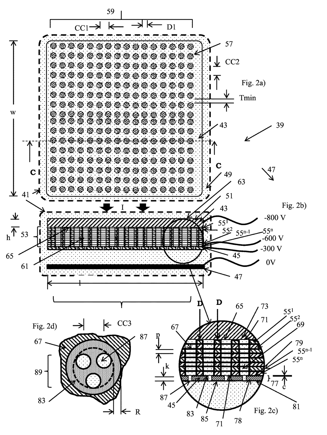
[0017]An example of a detecting unit (39) in accordance with an embodiment of the present invention is shown in FIGS. 2a) to 2d). This detecting unit (39) comprises a housing (41), shown by dashed lines, containing a converter unit (comprising a converter (43), a gas-electron multiplier (GEM) (45)), and a read-out unit (47) which generates signals relating to the position and intensity of electrons which interact with it. Signals generated in the read-out unit can be collected by a signal processing system (not shown) which may convert the signals into images. The housing is filled by a gas (49). Preferably the gas is a mixture of gases, preferably a Penning gas mixture, for example a mixture of argon-xenon or neon-argon.

[0018]The converter (43) is formed of a solid substrate (51) and a stack (53) formed of a plurality of perforated accelerator plates (551-55n), which have their perforations (57) aligned to form a regular matrix (59) of gas-filled blind holes (61). The solid substra...


PUM


Abstract

The invention relates to a detecting unit for detecting ionizing radiation. The device comprises a converter unit for the amplification of ionizing radiation and a read-out unit, wherein the converter unit comprises a converter and a gas-electron multiplier, wherein said converter comprises a substrate with an ionizing radiation-receiving major surface and an electron-emitting major surface and a stack of accelerator plates in contact with the electron-emitting major side, wherein said stack comprises a plurality of perforated accelerator plates wherein the perforations of the perforated accelerator plates are aligned to form a matrix of blind holes.

Description

TECHNICAL FIELD[0001]The present invention relates to a detecting device for ionizing radiation, converter units for such devices, as well as converters and gas electron multipliers for such converter units.BACKGROUND OF THE INVENTION[0002]In the medical field ionizing radiation has many diagnostic and therapeutic uses. It can be used for imaging the body of a patient for example to detect tumors and it can also be used for the treatment of a patient for example to irradiate detected tumors. In order to obtain good resolution images and accurately placed treatment it is necessary to detect the ionizing radiation after it has passed through the body being examined or treated and then process the signals obtained for the detecting means. The signals can be processed to obtain an image which represents the body through which it has passed and / or which represents the distribution of the ionizing radiation. In general the term “imaging” means forming an image of the measured data, and th...

Claims


Application Information

Patent Timeline
Patent Type & Authority Patents(United States)
IPC IPC(8): G01T1/18G01T1/17G01T1/29G01T1/185
CPCG01T1/185G01T1/2935G01T1/17
Inventor MAAD, KRISTOFERANDERSSON, MAURITZ
Owner BEAMOCULAR AB
Why Eureka
Try Eureka