Tactile warning surface mount panel for mounting on a preformed ground surface

a technology of tactile warning and surface mount, which is applied in the direction of physical therapy, construction, ways, etc., can solve the problems of preventing the efficient and frequent removal and replacement of tactile warning panels, and the need to remove and replace panels

Inactive Publication Date: 2018-02-20
BRANDBUMPS
View PDF151 Cites 6 Cited by
  • Summary
  • Abstract
  • Description
  • Claims
  • Application Information

AI Technical Summary

Benefits of technology

[0008]Accordingly, in some embodiments, the present invention provides surface mount panel assemblies comprising: a lower base plate directly attachable to an existing preformed ground surface, the lower base plate having a plurality of anchor holes therein for securing by anchoring the lower base plate to the preformed ground surface and a plurality of securement members therein that are offset from the anchor holes; and a removable upper panel having an upper surface, the upper panel having a plurality of through holes therein that register with the securement members when the upper panel is placed on the lower base plate so that the upper panel can be removeably secured to the lower plate.
[0018]In some embodiments, the lower base plate comprises a graphic display displaying at least two colors. In some embodiments, the graphic design displays at least three colors. In some embodiments, the graphic design has a resolution of at least 300×300 dots per inch. In some embodiments, the lower base plate is textured to provide slip resistance and durability. In some embodiments, the lower base plate comprises raised features to provide slip resistance. In some embodiments, the lower base plate comprises an array of raised, truncated domes that are in register with raised, truncated domes on the upper panel. In some embodiments, the lower base plate comprises a material selected from the group consisting of metal, polymeric materials, concrete, bricks, natural stone, ceramic, and tile. In some embodiments, the metal is selected from the group consisting of cast iron, ductile iron, steel, aluminum, and alloys thereof. In some embodiments, the polymeric material is selected from the group consisting of a plastic, thermoset plastic, thermoplastic, plastic composite, and fiber entrained plastic impregnated with carbon nanotubes, carbon black, or combinations thereof.
[0019]In some embodiments, the present invention provides surface mount panel assemblies comprising: a lower base plate directly attachable to a preformed ground surface, the lower base plate having a plurality of anchor holes therein for securing by an anchoring the lower base plate to the preformed ground surface and a first plurality of plastic reclosable fastener members distributed in a pattern on the lower base plate; a removable upper panel having an upper surface and a lower surface, the lower base plate surface comprising a second plurality of plastic reclosable fastener members distributed in a pattern that matches the pattern on the lower base plate so that the upper panel can be removeably secured to the lower base plate via the first and second plurality of plastic reclosable fastener members; and a plurality of anchors insertable through the anchor holes so that the lower base plate can be secured to the preformed ground surface.
[0021]In some embodiments, the present invention provides method for attaching to a preformed ground surface a surface mount assembly comprising a plurality of anchors, a plurality of fasteners, a lower base plate having a plurality of anchor holes therein and a plurality of receiver members therein that are offset from the anchor holes and a removable upper panel having a plurality of through holes therein that register with the receiver members, the method comprising: forming a plurality of counter sunk holes in the preformed ground surface that register with the receiver members in the lower base plate allowing for flush securement of the lower base plate with the preformed ground surface; attaching the lower base plate to the preformed ground surface with the plurality of anchors; and removeably attaching the upper panel to the lower base plate by inserting the fasteners through the through holes in the upper panel to engage the receivers in the lower base plate.

Problems solved by technology

These methods prevent the efficient and frequent removal and replacement of the tactile warning panel.
Tactile warning panels can be damaged by vehicles, chemical corrosion, ultra violet radiation, snowplows, foot traffic, as well as, general wear and tear from the harsh outdoor environment, thus requiring regular replacement.
Thus, as the messaging changes there is a need to remove and replace panels unrelated to repair or exigency.

Method used


Image

  • Tactile warning surface mount panel for mounting on a preformed ground surface
  • Tactile warning surface mount panel for mounting on a preformed ground surface
  • Tactile warning surface mount panel for mounting on a preformed ground surface

Examples


first embodiment

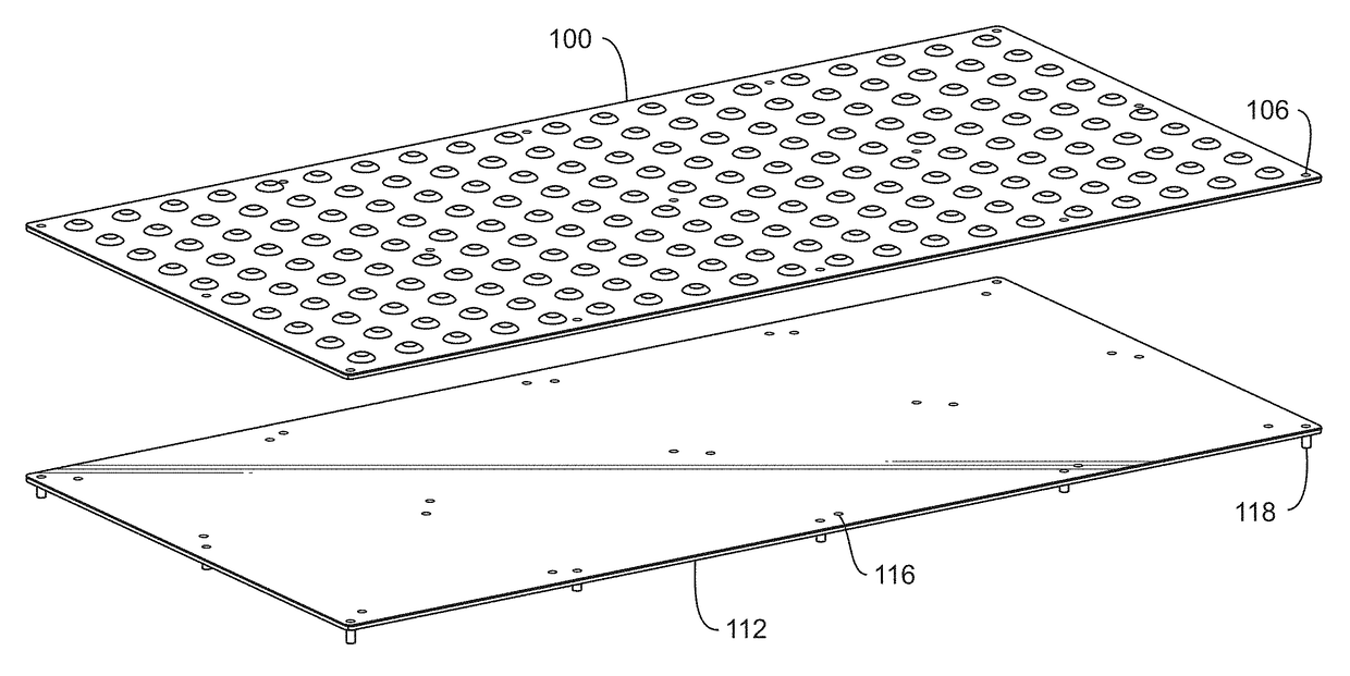
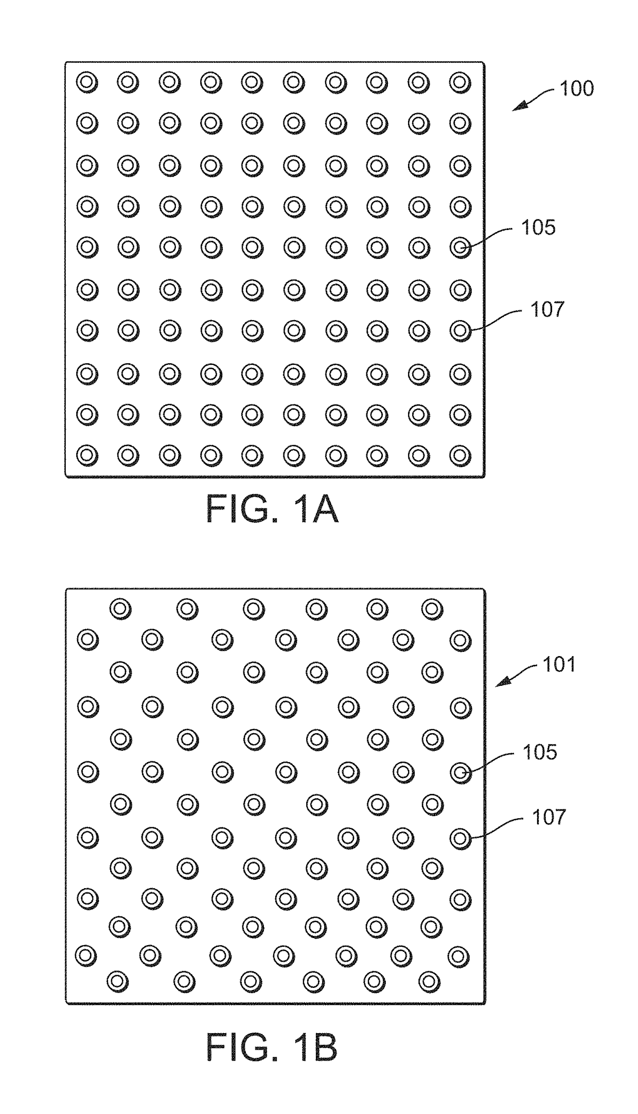
[0167]The first embodiment for the tactile warning surface mount double panel assembly consists of an upper panel as illustrated in FIG. 5A. FIG. 5A illustrates a tactile warning surface mount upper panel 100 incorporating an attention pattern constructed of a solid substrate 102 that can be manufactured out of multiple types of material. The most common types of material for tactile warning panels include steel or plastic composite materials. The upper panel 100 contains a plurality of upward projections 104 extending upwards from the surface of the solid member substrate 102 and a number of round through-holes 106. Each projection 104 generally consists of a raised surface called a truncated dome, as illustrated in FIG. 5B. FIG. 5B illustrates the truncated dome extending upward 108 from the solid substrate, FIG. 5A, 102 to a top flat section 110. FIG. 5C illustrates that the design of this particular upper tactile panel utilizes round through-holes 106 around the perimeter and in...

second embodiment

[0174]The second embodiment for a tactile warning surface mount panel double panel assembly comprises an upper tactile panel as shown on FIG. 14A. FIG. 14A illustrates a tactile warning surface mount panel 200 incorporating an attention pattern on a solid substrate member 102. The upper tactile panel 200 contains a plurality of upward projections 104, extending upward from the surface of the solid member 102. Each upward projection 104 generally consists of a surface rising from a perimeter FIG. 11, 108 to a central top portion FIG. 11, 110. FIG. 14A illustrates the second design of the upper tactile panel 200, which utilizes a keyhole through-hole 206 design for the through-holes in the upper tactile panel 200. These keyhole through-holes 206 are used to secure the upper tactile panel 200 to the lower base plate. The keyhole through-holes 206 in the upper tactile panel 200 are an improvement over round through-holes and assist in the alignment of the upper tactile panel 200 through...

third embodiment

[0175]The third embodiment for the tactile warning surface mount double panel assembly consists of an upper tactile panel as illustrated on FIG. 21A. FIG. 21A illustrates an upper panel 624 incorporating an attention pattern constructed of a solid substrate 102. The upper panel 624 contains a plurality of upward projections 104 extending upwards from the surface of the solid substrate 102. Each upward projection 104 generally consists of a surface rising from a perimeter FIG. 11, 108 to a central top portion FIG. 11, 110. FIG. 21A illustrates the third design of the upper panel, which utilizes teardrop through-holes 626 in the upper panel 624. These teardrop through-holes are used to secure the upper panel 624 to a lower base plate. The teardrop through-hole 626 in the upper panel 624 is an improvement over round through-holes FIG. 5A, 106 and assist in the alignment of the upper panel 624 teardrop through-holes 626 with the receivers in the lower base plate. FIG. 21B illustrates an...


PUM


Abstract

Methods of installation, securement, removal and replacement of tactile warning surface mount plates / panels (TWSP's), preferably having at least a two color graphic design thereon, on pedestrian walkways, driveways, sidewalks, ramps, handicap ramps, retail floors and other types of existing preformed ground surfaces. The present invention includes TWSP's for both attention plates / panels and guiding plates / panels.

Description

CROSS REFERENCE TO RELATED APPLICATIONS[0001]This application claims the benefit of the U.S. Provisional Application 61 / 954,924, filed on Mar. 18, 2014, the entire contents of which are incorporated herein by reference.FIELD OF THE INVENTION[0002]The present invention relates to the means and methods of installation, securement, removal and replacement of tactile warning surface mount plates / panels (TWSP's), preferably having at least a two color graphic design thereon, on pedestrian walkways, driveways, sidewalks, ramps, handicap ramps, retail floors and other types of existing preformed ground surfaces. The present invention includes TWSP's for both attention plates / panels and guiding plates / panels.BACKGROUND OF THE INVENTION[0003]There are numerous ways to secure to existing preformed ground surfaces objects, fixtures, structures, plates, panels, beams and other items using many different types of fastening systems and / or fasteners. The existing preformed ground surfaces could be...

Claims


Application Information

Patent Timeline
Patent Type & Authority Patents(United States)
IPC IPC(8): A61H3/06E01C5/00
CPCE01C5/001A61H3/066
Inventor HENSHUE, CHRISTOPHER GARYHENSHUE, GARY LAVERNE
Owner BRANDBUMPS
Why Eureka
Try Eureka