Haptic feedback stylus and other devices

a technology of haptic feedback and stylus, which is applied in the field of interface devices, can solve the problems of high manufacturing cost of such devices, and high cost of devices for consumers, and achieve the effect of simple and lower cost force feedback

Inactive Publication Date: 2007-09-04
IMMERSION CORPORATION
View PDF195 Cites 114 Cited by
  • Summary
  • Abstract
  • Description
  • Claims
  • Application Information

AI Technical Summary

Benefits of technology

[0006]The present invention is directed to a low-cost force feedback interface which provides a linear actuator along a non-primary axis or degree of freedom. This

Problems solved by technology

One problem with current force feedback controllers in the home consumer market is the high manufacturing cost of such devices, which makes the devices expensive for the consumer.
A large part of this manufacturing expense is due to the inclusion of multiple ac

Method used


Image

  • Haptic feedback stylus and other devices
  • Haptic feedback stylus and other devices
  • Haptic feedback stylus and other devices

Examples


embodiment 150

[0060]The mouse embodiment 150 allows the user to interact with a graphical environment through the sense of feel. The output of forces can be coordinated with events occurring in the graphical environment. For example, when the user moves a cursor over a window in a graphical user interface, a jolt can be output by actuator 100 as the cursor moves over a boundary of the window. Furthermore, the magnitude of output forces can depend on the event in the graphical environment. For example, the force jolt can be a different magnitude of force depending on the type of graphical object encountered by the cursor. For example, a jolts of higher magnitude can be output when the cursor moves over windows, while jolts of lower magnitude can be output when the cursor moves over icons. The magnitude of the jolts can also depend on other characteristics of graphical objects, such as an active window as distinguished a background window, file folder icons of different priorities designated by the...
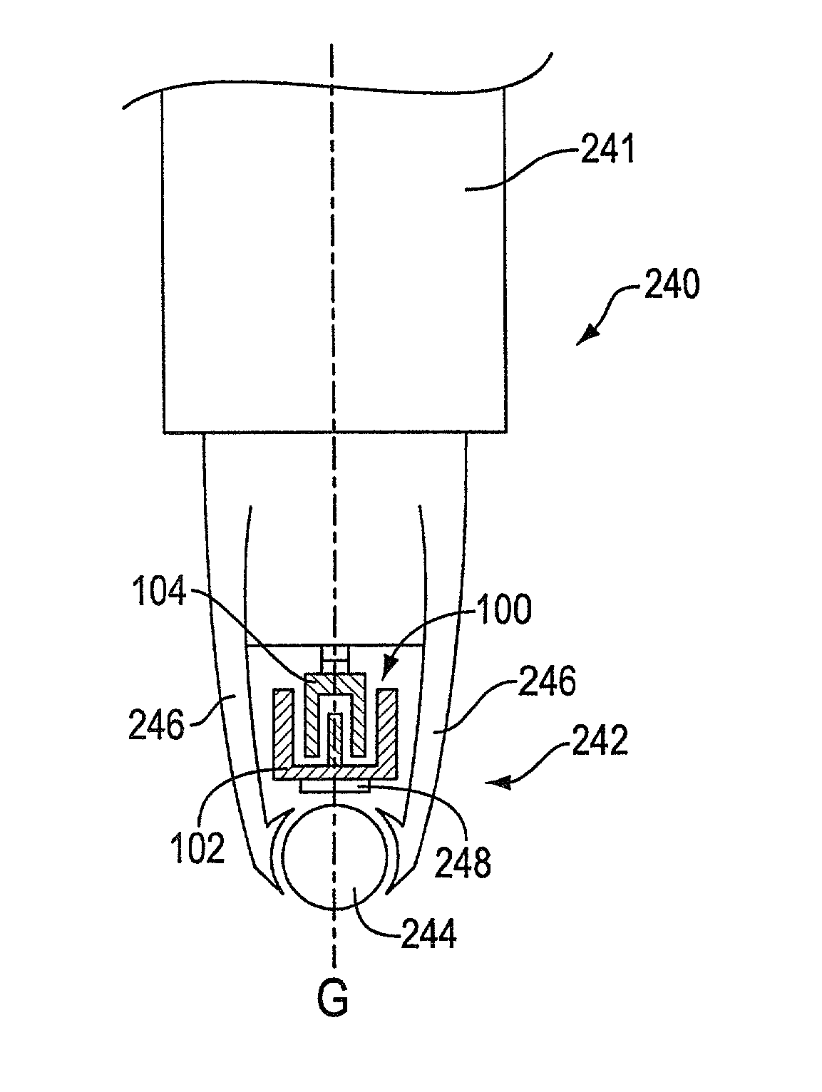
embodiment 240

[0068]When the user wishes to use the stylus normally, the user moves the tip of the pen across a surface. Since the ball 244 is the only portion of the tip contacting the surface in typical operation, this motion causes the ball 244 to roll to allow a fluid motion of the stylus over the surface. The contact of the ball with a tablet surface can be sensed by a sensor in the tablet, for example. When a force sensation is to be output, the actuator 100 is controlled to extend, i.e. the housing 102 and brake pad 248 are commanded to move and contact the ball 244. This causes a resistance to the motion of the ball and can cause the ball to stop rolling. If the actuator 100 is commanded to quickly move the brake pad 248 against the ball 244 with maximum force, a jolt-like effect is felt by the user. If the brake pad is more gradually contacted with the ball, the user may feel an increasing resistance or damping-like effect. If the actuator is commanded to pulse so that the brake pad 248 ...


PUM


Abstract

A force feedback interface and method including an actuator in a non-primary axis or degree of freedom. The force feedback interface device is connected to a host computer that implements a host application program or graphical environment. The interface device includes a user manipulatable object, a sensor for detecting movement of the user object, and an actuator to apply output forces to the user object. The actuator outputs a linear force on the user object in non-primary linear axis or degree of freedom that is not used to control a graphical object or entity implemented by the host computer, and movement in the non-primary degree of freedom is preferably not sensed by sensors. The axis extends through the user object, and there are preferably no other actuators in the device, thus allowing the force feedback device to be very cost effective. Force sensations such as a jolt, vibration, a constant force, and a texture force can be output on the user object with the actuator. The force sensations can be output in a direction perpendicular to a planar degree of freedom, radial to spherical degree of freedom, and/or along a lengthwise axis of the user object.

Description

[0001]This is a continuation application of copending U.S. application Ser. No. 09 / 563,783, filed May 2, 2000 now U.S. Pat. No. 6,353,427, which is a continuation of U.S. application Ser. No. 09 / 103,281, now U.S. Pat. No. 6,088,019, filed Jun. 23, 1998, the disclosures of which are incorporated herein by reference in their entireties.BACKGROUND OF THE INVENTION[0002]The present invention relates generally to interface devices for allowing humans to interface with computer systems, and more particularly to computer interface devices that allow the user to provide input to computer systems and allow computer systems to provide force feedback to the user.[0003]A computer system in typical usage by a user displays a visual environment on a display output device. Using an interface device, the user can interact with the displayed environment to perform functions and tasks on the computer, such as playing a game, experiencing a simulation or virtual reality environment, using a computer a...

Claims


Application Information

Patent Timeline
IPC IPC(8): G09G3/28G06F3/043A63F13/06G06F3/00G06F3/01G06F3/033H04L29/08
CPCA63F13/06G06F3/011G06F3/016G06F3/0338G06F3/03543G06F3/03545G06F3/0362A63F2300/1037A63F2300/1062A63F2300/1068A63F2300/8017G06F2203/013G06F2203/014G06F2203/015H04L69/329A63F2300/1006A63F13/803A63F2300/1087A63F13/285A63F13/23A63F13/426A63F13/213A63F13/245A63F2300/1025A63F2300/6081A63F13/54
Inventor ROSENBERG, LOUIS B.
Owner IMMERSION CORPORATION
Why Eureka
Try Eureka