
Force reflecting haptic interface

a technology of haptic interface and force, applied in the field of interface, can solve the problems of user not being able to distinguish between touching a real object and touching a virtual object with the device, designing stiff, and difficult to uncouple transmissions for them, and achieves a high degree of realism, accurate perception of conditions, and facilitates high-fidelity position and torque or force feedback

Inactive Publication Date: 2005-02-08
MASSACHUSETTS INST OF TECH
View PDF188 Cites 116 Cited by
  • Summary
  • Abstract
  • Description
  • Claims
  • Application Information

AI Technical Summary

Benefits of technology

include, to enable human interaction with a non-local environment, either physical or computer represented, with a high degree of realism. It is an object to facilitate a high fidelity position and torque or force feedback, so that the user has an accurate perception of the conditions in the non-local environment. The user interface should be transparent to the user and as unobtrusive as possible. Implicit in this object is to minimize system backlash. It is further an object to provide such an interface that permits use...

Problems solved by technology

However, the entire arm assembly may have many more than these six freedoms, due to the numerous joints and their various flexibilities.
Specifically, a user would not be able to distinguish between touching a real object and touching a virtual object with the device.
There are many constraints in the design of an exoskeleton device, because the structure must attach to several locations on the human body and the exoskeleton joints must effectively be co-located with human joints.
Counterbalancing such structures, and designing stiff, uncoupled transmissions for them is difficult.

Method used


Image

  • Force reflecting haptic interface
  • Force reflecting haptic interface
  • Force reflecting haptic interface

Examples


Embodiment Construction

The present invention includes an apparatus that can be used to interact with a “non-local” environment, either real or virtual. The virtual environment can be of a typical computer data processing type, or of a less common, more specialized type.

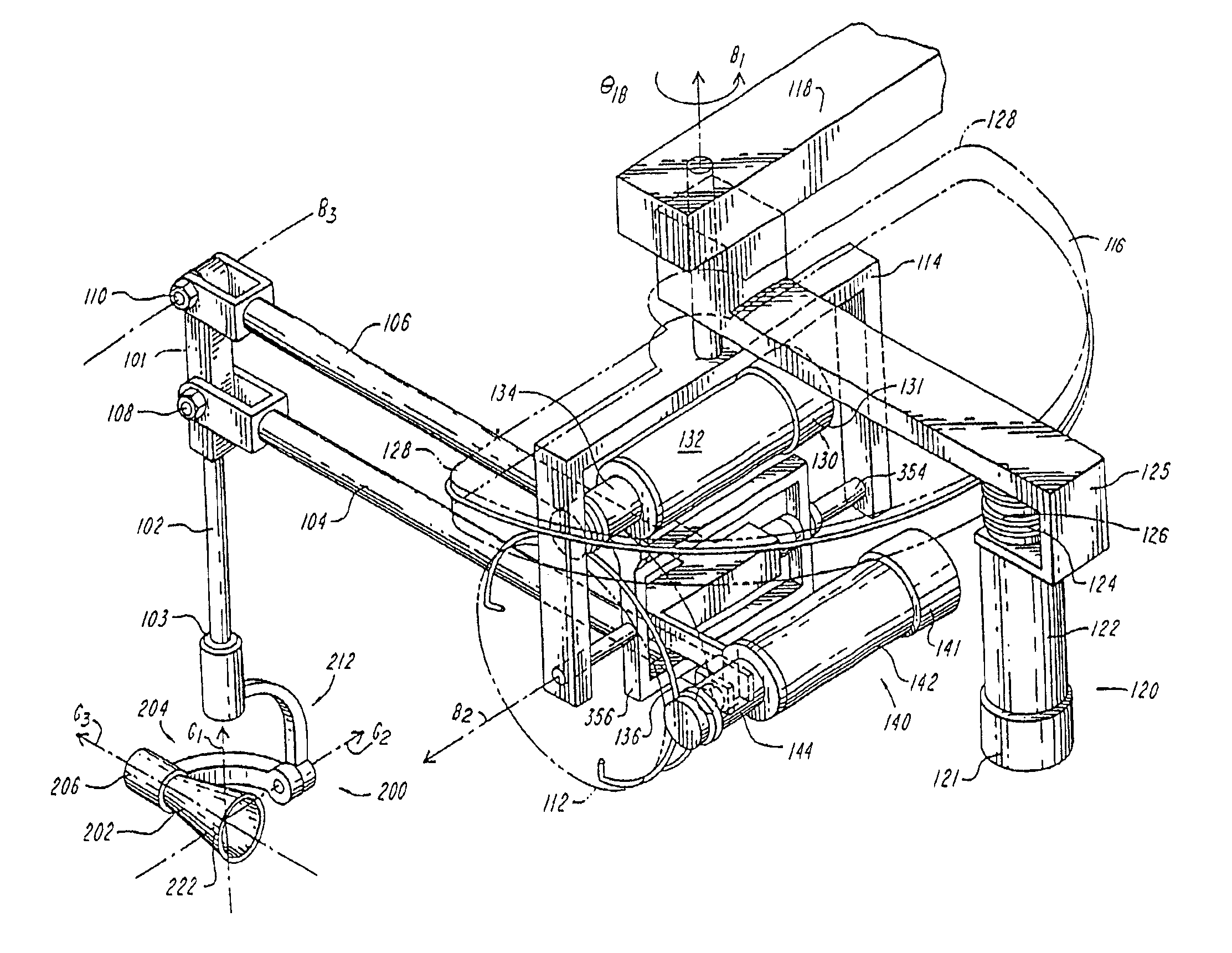
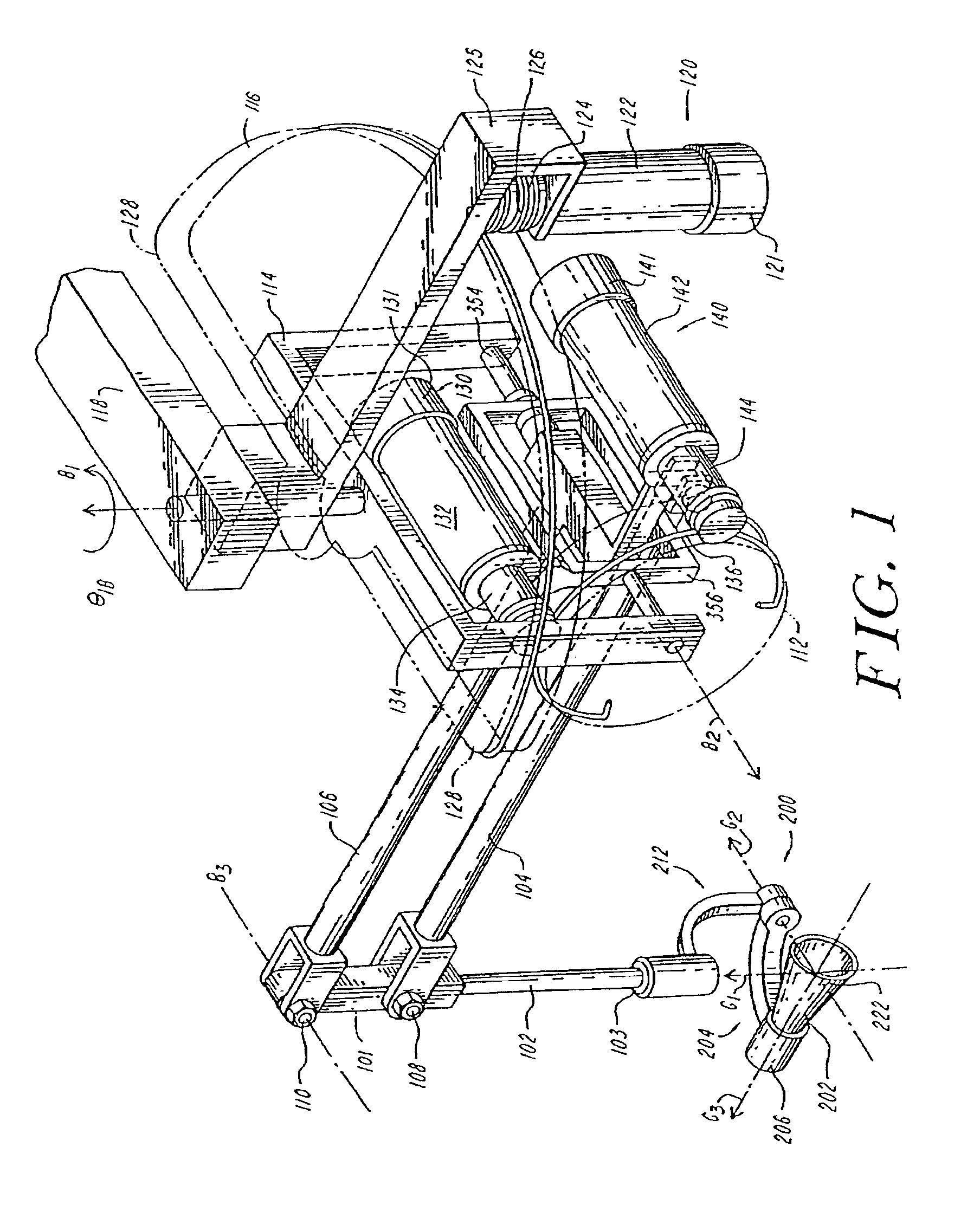
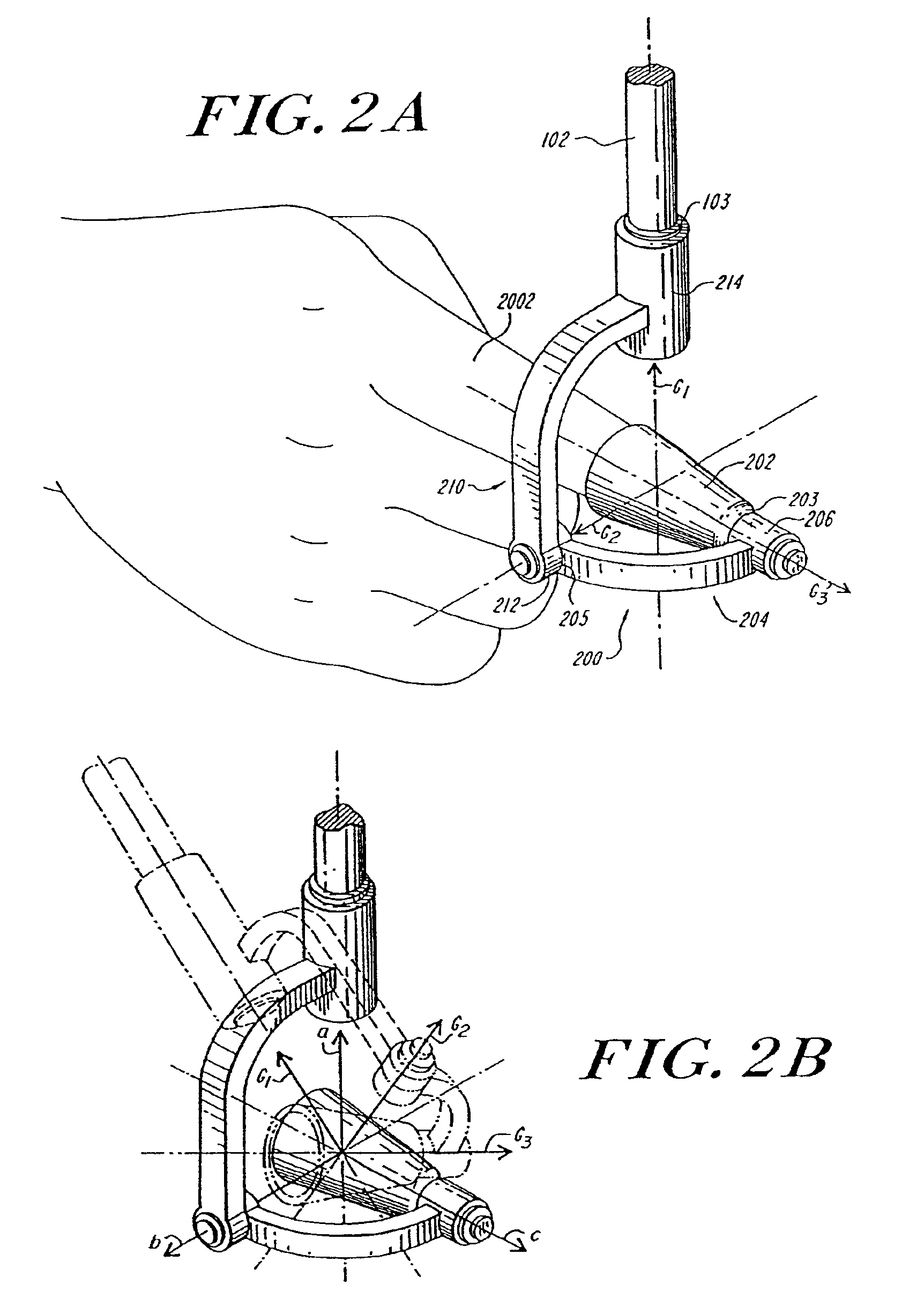
In one embodiment, a thimble is provided for engaging a user's finger. The thimble is supported through a linkage such that three freedoms of motion are provided for the user's finger that are totally “unpowered.” By unpowered, or “free of power”, it is meant that they are not powered, nor is there any resistance (e.g. friction or damping) to motion through these freedoms. (The status or position of motion through these unpowered freedoms may or may not be tracked. If they are not tracked, they are referred to herein as “free.”) In the same embodiment, the linkage is arranged such that three additional freedoms of motion are “powered.” By powered, it is meant that the device has the capability to resist or assist motion through these freedo...


PUM


Abstract

The invention is an apparatus for physically exchanging a force with a user in an environment local to the user. A connection element connects to a user's body member and a linkage between the connection element and ground. The linkage includes means for powering at least three independent freedoms of the connection element relative to ground and means for maintaining at least one independent freedom of the connection element relative to ground free of power. Up to three independent freedoms of the connection element may be maintained free of power, and up to five independent freedoms may be powered. Other aspects of the invention include a two actuator counter-balance for controlling a point on a link. The invention also includes apparatus for establishing a virtual, switch, which presents to the user the force and displacement relationship of a spring switch. Another embodiment is a virtual bristled brush, again which presents to the user the force and displacement relationship of such a brush, while also changing the virtual environment to reflect the user's changes in location.

Description

BACKGROUNDThe present invention relates generally to an interface between an operator and a machine. It relates more specifically to the field of such interfaces which present a signal to a human operator in contact with the interface. The invention relates most specifically to an interface that presents or exhibits a force signal to an operator, such as a human, or receives a force signal from such an operator. Because a force signal is by definition bi-directional, it can be said that the interface and the user “exchange” a force signal, or “share” it with each other.Machines are ubiquitous in modem life, and every machine must be controlled, either directly or indirectly by a human operator. The interface through which the operator controls the machine and receives information from the machine should be as easy to use as possible, in light of the functionality the machine provides. Examples of such machines include slave robotic machines that operate in an environment different f...

Claims


Application Information

Patent Timeline
IPC IPC(8): G05B11/01G09G5/00G06G7/48G06G7/00B25J9/16B25J13/02G05G1/52G05G9/047G06F3/00G06F3/01G06F3/033G06F3/038
CPCB25J9/1689B25J13/02G05B17/02G05G1/52G05G9/047G06F3/014G06F3/016G06F3/033G06F3/0346G06F3/0383G05B2219/23021G06F2203/0331G05G2009/04766G06G7/48G05B11/01
Inventor MASSIE, THOMAS HSALISBURY, JR., J. KENNETH
Owner MASSACHUSETTS INST OF TECH
Learn More